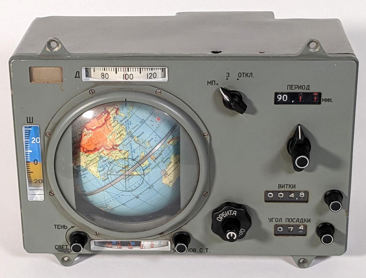
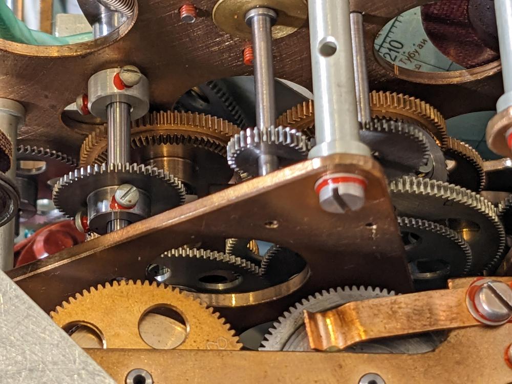
In the Soyuz space missions, cosmonauts tracked their position above the Earth with a remarkable electromechanical device with a rotating globe. This navigation instrument was an analog computer that used an elaborate system of gears, cams, and differentials to compute the spacecraft's position. Officially, the unit was called a "space navigation indicator" with the Russian acronym ИНК (INK),1 but I'll use the nickname "Globus".
We recently received a Globus from a collector and opened it up for repair and reverse engineering. Although the Globus does all its calculations mechanically, it has some electronics to control the motors. Inconveniently, all the wires in the wiring harness to the external connector had been cut so I had to do some reverse engineering before we could power it up. In this blog post, I explain how the electronics operate. (For an overview of the mechanical components inside the Globus, see my previous article.)
Functionality
The primary purpose of the Globus is to indicate the spacecraft's position. The globe rotated while fixed crosshairs on the plastic dome indicated the spacecraft's position. Thus, the globe matched the cosmonauts' view of the Earth, allowing them to confirm their location. Latitude and longitude dials next to the globe provided a numerical indication of location. The light/shadow dial at the bottom showed when the spacecraft would be illuminated by the sun or in shadow.
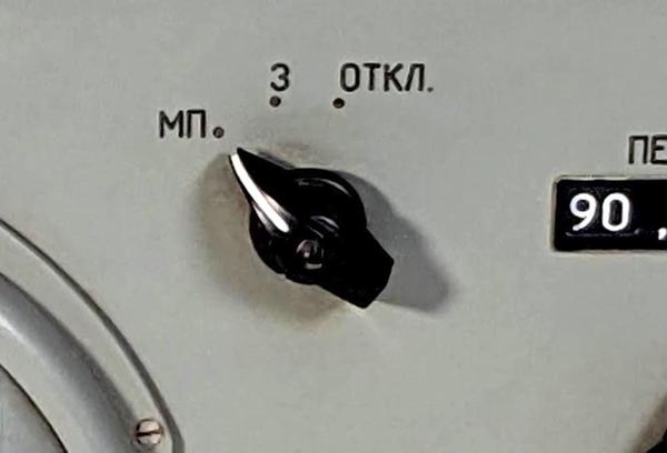
The mode of the Globus is controlled by a three-position rotary switch near the top of the Globus. The middle position "З" (Земля, Earth) shows the position of the spacecraft over the Earth. The left position, "МП" (место посадки, landing site) selects the landing position mode. The third position "Откл" (off) turns off most of the Globus. This rotary switch is surprisingly complicated with three wafers, each with two poles. Most of the electronics go through this switch, so this switch will appear often in the schematics below.
In the landing position mode, the Globus rotates to show where the spacecraft would land if you fired the retrorockets now. This allowed the cosmonauts to evaluate the suitability of this landing site. This position is computed simply by rapidly rotating the globe through a fraction of an orbit, since the landing position will be on the current orbital track. Most of the electronics in the Globus control the motor that performs this rotation.
Overview of the electronics
The Globus is primarily mechanical, but it has more electrical and electronic components than you might expect. The mechanical motion is powered by two solenoids with ratchets to turn gears. The landing site mode is implemented with a motor to rotate to the landing position, controlled by two limit switches. An electroluminescent light indicates the landing position mode. A potentiometer provides position feedback to external devices.
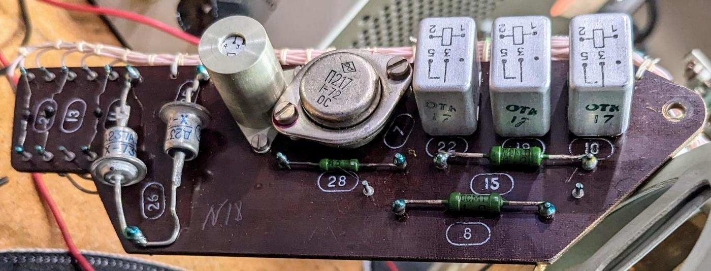
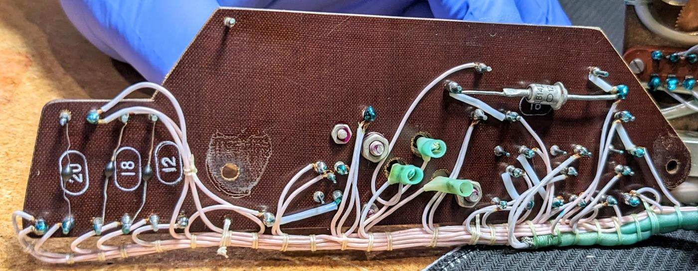
To control these components, the Globus has an electronics board with four relays, along with a germanium power transistor and some resistors and diodes.2 Bundles of thin white wires with careful lacing connect the electronics board to the other components.
The back of the circuit board has a few more diodes. The wiring is all point-to-point; it is not a printed-circuit board. I will explain the circuitry in more detail below.
The drive solenoids
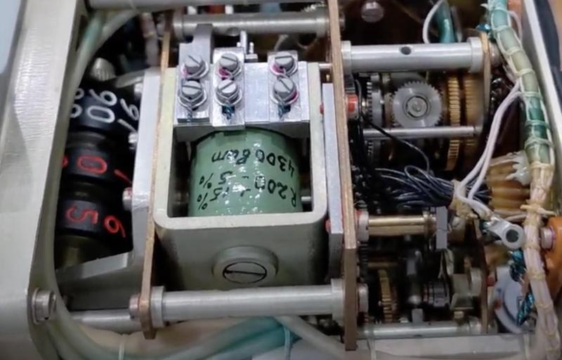
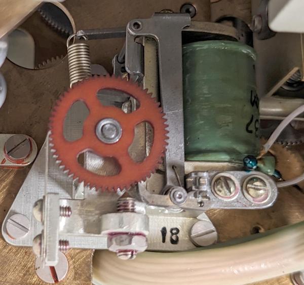
The Globus contains two ratchet solenoids: one for the orbital rotation and one for the Earth's rotation. The complex gear trains and the motion of the globe are driven by these solenoids. These solenoids take 1-hertz pules of 27 volts and 100ms duration. Each pulse causes the solenoid to advance the gear by one tooth; a pawl keeps the gear from slipping back. These small rotations drive the gears throughout the Globus and result in a tiny movement of the globe.
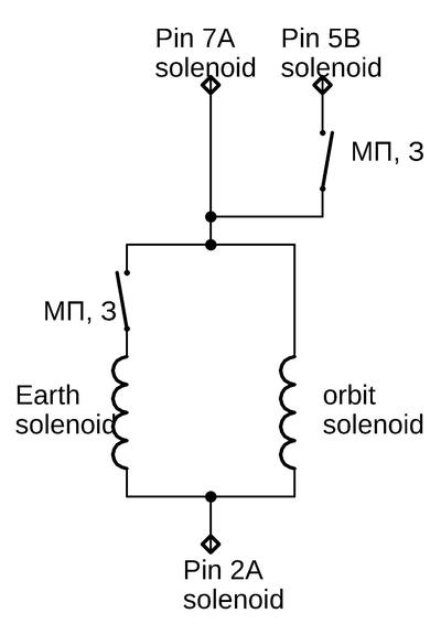
As the schematic shows, the solenoids are controlled by two switches that are closed in the МП (landing position) and З (Earth orbit) modes. The solenoids are powered through three pins. The wiring doesn't entirely make sense to me. If powered through pins 2A and 7A, the Earth motor is switched while the orbit motor is always powered. But if powered through pins 2A and 5B, both motors are switched. Maybe pin 7A monitors the on/off status of the Globus.
By powering the solenoids with 1 hertz pulses, we caused the Globus to rotate. The motion is very slow (90 minutes for an orbit and one day for the Earth's rotation), so we tried overclocking it at 10 hertz. This made the motion barely visible; Marc used a time-lapse to speed it up in the video below.
The landing location mechanism
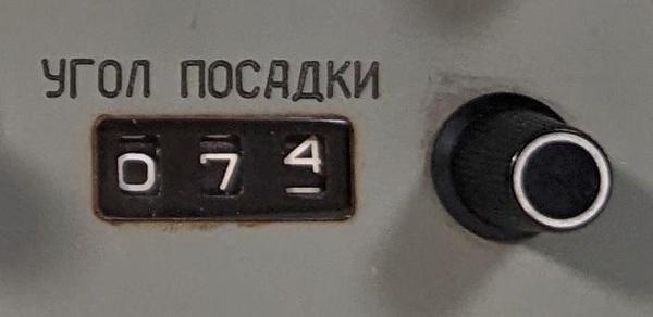
The Globus can display where the spacecraft would land if you started a re-entry burn now, with an accuracy of 150 km. This is computed by projecting the current orbit forward for a particular distance, specified as an angle. The cosmonaut specifies this value with the landing angle knob (details). Rotating the globe to this new position is harder than you might expect, using a motor, limit switches, and the majority of the electronics in the Globus.
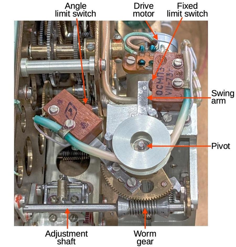
The landing angle knob pivots the angle limit switch, shown below. The swing arm moves as the globe rotates to the landing position and hits the angle limit switch when the landing position is reached. When returning to Earth orbit mode, the swing arm swings back until it hits the fixed limit switch. Thus, the globe is rotated by the selected amount when displaying the landing position.
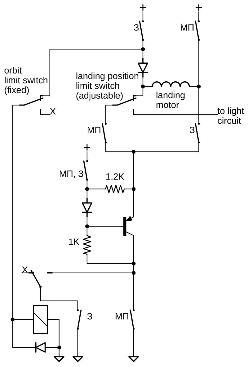
To control the motor, the rotary switch reverses the DC motor based on the mode, while the limit switches and power transistor turn the motor on and off. In landing position mode (МП), the motor spins the globe forward. The mode switch controls the direction of current flow: from upper right, through the motor, through the angle limit switch, through the transistor, and to ground at the bottom. The motor will rotate the globe and the arm until it hits the "landing position" limit switch, cutting power to the motor and activating the path to the light circuit, which I will discuss below. The diode prevents current flowing backward through the motor to the relay. The power transistor apparently acts as a current sink, regulating the current through the motor.
In Earth orbit mode (З), the motor spins the globe back to its regular position. The mode switch reverses the current flow through the motor: from the upper-left, through the diode and the motor, and out the lower-right to the transistor. At the bottom, the relay completes the circuit until the moving arm hits the fixed orbit limit switch. This opens the normally-closed contact, cutting power to the relay, opening the relay contact, and stopping the motor.
The landing place light
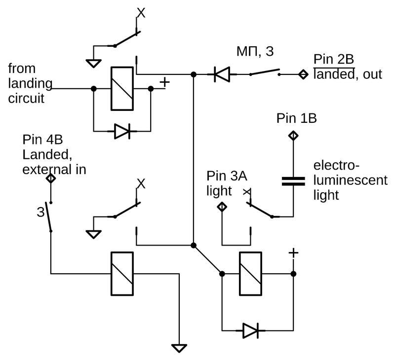
The upper-left corner of the Globus has an electroluminescent light labeled "Место посадки" (Landing place). This light illuminates when the globe indicates the landing place rather than the orbital position. The light is powered by AC provided on two external pins and is controlled by two relays. One relay is activated by the landing circuit described above, when the limit switch closes. The second relay is driven by an external pin. I don't know if this is for a "lamp test" or control from an external system.
We powered the light with an EL inverter from Adafruit, which produces 100 VAC at 2KHz, perhaps. The spacecraft used a "Static Inverter" to power the light, but I don't have any details on it. The display provides a nice blue glow.
The potentiometer
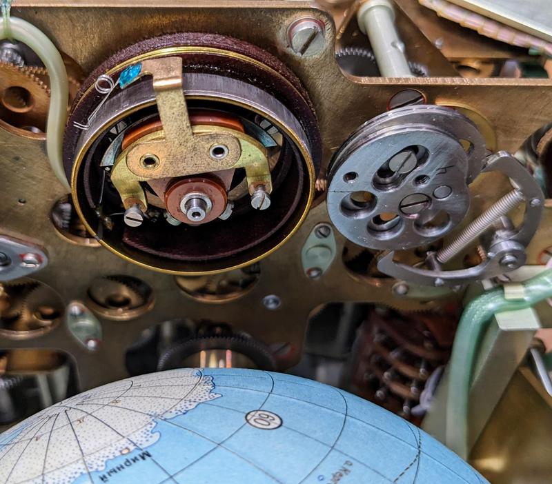
A 360° potentiometer (below) converts the spacecraft's orbital position into a resistance. Sources indicate that the Globus provides this signal to other units on the spacecraft, but I don't know specifically what these devices are. The potentiometer appears to linearly track the spacecraft's position through the orbital cycle. Note that this is not the same as the latitude, which oscillates, or the longitude, which is non-linear.
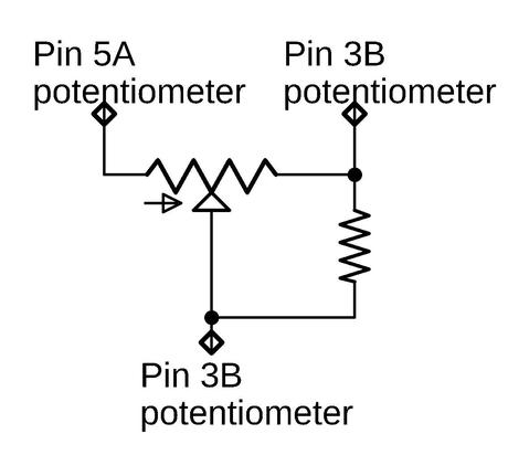
As the schematic below shows, the potentiometer has a resistor on one leg for some reason.
The external connector
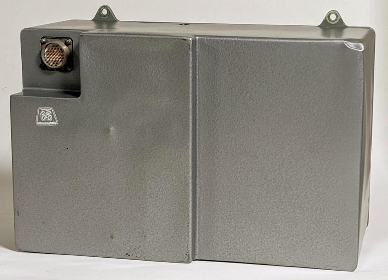
To connect the Globus to the rest of the spacecraft, the back of the Globus has a 32-pin connector, a standard RS32TV Soviet military design.
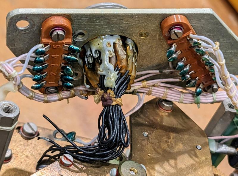
The connector was wired to nearby 5-pin and 7-pin terminal strips. In the schematics, I label these connectors as "B" and "A" respectively. Inconveniently, all the wires to the box's external connector were cut (the black wires), perhaps to decommission the unit. The pinout of the external connector is unknown so we can't easily reconnect the wires.
Conclusions
By tracing out the wiring of the Globus, I determined its circuitry. This was more difficult than expected, since the wiring consists of bundles of identical white wires. Moreover, many things go through the mode switch, and its terminals were inaccessible. Between the mode switch and the limit switches, there were many cases to check.
Once I determined the circuitry, we could power up the Globus. So far, we have powered the solenoids to turn the Globus. We also illuminated the landing position light. Finally, we ran the landing position motor.
Follow me on Twitter @kenshirriff or RSS for updates. I've also started experimenting with Mastodon recently as @oldbytes.space@kenshirriff. Many thanks to Marcel for providing the Globus.
Notes and references
-
In Russian, the name for the device is "Индикатор Навигационный Космический" abbreviated as ИНК (INK). This translates to "space navigation indicator." ↩
-
Most of the diodes are flyback diodes, two diodes in series across each relay coil to eliminate the inductive kick when the coil is disconnected. ↩

I love your website. I think it's amazing that there are people who can figure things like this out.
ReplyDeleteIt reminds me of college. I went to RPI, but was NOT an engineering major.
All the time I ran into people who were amazingly intelligent in just this way, they could quickly figure out how a Globus worked after staying up all night to prepare for the final after skipping most all of the classes and still acing the test.
greetings from the Czech republic
ReplyDeletetwo of the three contacts of the potentiometer are marked the same (as pin 3B), this is probably a mistake
but congrats on the great reverse engineering
Petr Kohout
The resistor on the poteniometer may be to prevent the wiper side from being open, even intermittently.
ReplyDeleteThe resistor R causes a non-linear behaviour of the linear potentiometer. Let the potentiometer be R1+R2. Instead a voltage across R2 proportional to R2/(R1+R2) it replaces R2 by R2//R
Delete