The 8086 processor was introduced in 1978 and has greatly influenced modern computing through the x86 architecture. One unusual instruction in this processor is HLT, which stops the processor and puts it in a halt state. In this blog post, I explain in detail how the halt circuitry is implemented and how it interacts with the 8086's architecture.
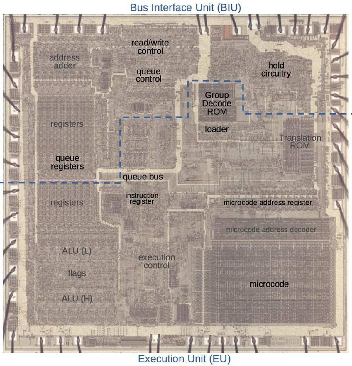
The die photo below shows the 8086 microprocessor under a microscope. The metal layer on top of the chip is visible, with the silicon and polysilicon mostly hidden underneath. Around the edges of the die, bond wires connect pads to the chip's 40 external pins. I've labeled the key functional blocks; the ones that are important to this discussion are darker and will be discussed in detail below. Architecturally, the chip is partitioned into a Bus Interface Unit (BIU) at the top and an Execution Unit (EU) below. The BIU handles memory accesses, while the Execution Unit (EU) executes instructions. Both are stopped by a halt instruction.
Halt processing in the Execution Unit
In this section, I'll explain how the HLT instruction is decoded and handled in the Execution Unit. The 8086 uses a combination of lookup ROMs, logic, and microcode to implement instructions. The process starts with the loader, a state machine that provides synchronization between the prefetch queue and the decoding circuitry. When an instruction byte is available, the loader provides a signal called First Clock that loads the instruction into the Instruction Register and starts the instruction decoding process.
Before microcode gets involved, the Group Decode ROM classifies instructions by producing about 15 signals, indicating properties such as instructions with a Mod R/M byte, instructions with a byte/word bit, instructions that always act on a byte, and so forth. For the HLT instruction, the Group Decode ROM provides two important signals. The first is one-byte logic (1BL), indicating that the instruction is one byte long and is implemented with logic circuitry rather than microcode.1 The second signal is produced for the HLT instruction specifically and generates the internal HALT signal. This signal travels to various parts of the 8086 to halt the processor.
In the Execution Unit, the HALT signal blocks the reading of new instructions from the prefetch queue. This causes the loader to wait indefinitely and stops execution of new instructions. Since no new instruction replaces HLT, the Group Decode ROM continues to generate the HALT signal. The HALT signal also blocks most of the other outputs from the Group Decode ROM, preventing other decoding actions.
Thus, the Execution Unit sits idle as a result of the HLT instruction, unable to start a new instruction. Modern processors often have low-power halt modes, where part of the processor is shut down or a clock domain is stopped to reduce power consumption. The 8086, however, doesn't do anything clever to minimize power consumption in the halt mode, since this wasn't a concern for processors in the 1970s.
Halt processing in the Bus Interface Unit
Memory and I/O devices are connected to the 8086 chip through a bus that transmits address, data, and control information. The 8086's Bus Interface Unit handles reads and writes over this bus, running independently from the Execution Unit. A complete bus cycle for a read or write takes four clock periods, called T1, T2, T3, and T4,2 with specific signals on the bus for each time state.
A HLT instruction stops the Bus Interface Unit, but this takes several steps. First, the Bus Interface Unit must complete any currently-running bus cycle. Any new bus cycle must be blocked. Finally, the processor indicates the HALT state to any devices on the bus by issuing a special T1 cycle over the bus.
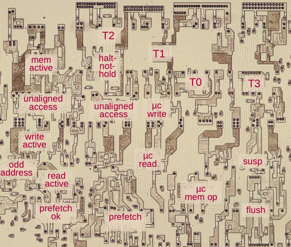
The main HALT control signal inside the Bus Interface Unit is something I call halt-not-hold, indicating a HALT is active,
but not a HOLD. (Ignore the HOLD part for now.)
This signal is activated by the HLT instruction signal from the Group Decode ROM, except it is blocked by
any bus operations in progress. Once any current bus operation reaches T2, halt-not-hold gets activated and
starts the halt process while the current bus cycle finishes up.
To prevent new bus activity,
the halt-not-hold signal blocks new prefetch requests.
The only other source of bus activity is an instruction that performs reads or writes.
But the current instruction is HLT, so it won't generate any bus traffic.
Thus, the Bus Interface Unit will remain idle.
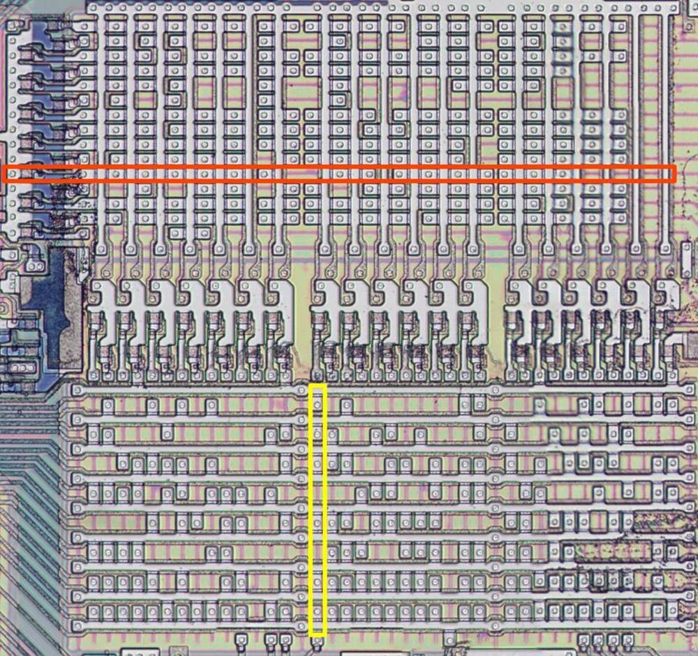
The circuitry to control the bus cycle is complicated with many flip-flops and logic gates; the diagram above shows the flip-flops. I plan to write about the bus cycle circuitry in detail later, but for now, I'll give an extremely simplified description. Internally, there is a T0 state before T1 to provide a cycle to set up the bus operation. The bus timing states are controlled by a chain of flip-flops configured like a shift register with additional logic: the output from the T0 flip-flop is connected to the input of the T1 flip-flop and likewise with T2 and T3, forming a chain. A bus cycle is started by putting a 1 into the input of the T0 flip-flop.3 When the CPU's clock transitions, the flip-flop latches this signal, indicating the (internal) T0 bus state. On the next clock cycle, this 1 signal goes from the T0 flip-flop to the T1 flip-flop, creating the externally-visible T1 state. Likewise, the signal passes to the T2 and T3 flip-flops in sequence, creating the bus cycle.
A slightly different path is used to generate the special T1 signal that indicates a HALT.
Once any bus activity is completed, the halt-not-hold signal puts a 1 into the T1 flip-flop through some gates.
This generates the T1 signal, bypassing T0.
Moreover, this signal does not propagate to the T2 flip-flop because it is blocked by halt-not-hold and some gates.
Another flip-flop blocks this T1 cycle after the first cycle so halt-not-hold doesn't repeately trigger it.
Overall, this special HALT T1 state looks like a special case that was hacked into the circuitry.
One complication is the bus hold feature. The 8086 supports complex bus configurations, where external devices may take control of the bus. For instance, peripherals may use the bus for direct memory access, bypassing the CPU. A device can request control of the bus, a "bus hold", through the 8086's HOLD pin.4 This causes the 8086 to electrically stop putting signals on the bus (i.e. a high-impedance, tri-state off state). This allows another device to use the bus until it releases HOLD.
Even when the CPU is halted, the CPU still has "ownership" of the bus and drives the bus with idle signals.5
If a device requests a bus hold when the CPU is halted, the halt-not-hold signal is blocked.
When the device releases the hold, halt-not-hold is unblocked.
This causes the 8086 to go through the special T1 cycle again, using the same flip-flop process described above.
This lets listeners on the bus know that the CPU is still halted.
Exiting the halt state
The processor exits the halt state when it receives a reset, interrupt, or non-maskable interrupt. To implement this, an interrupt unblocks the instruction decoder by overriding the queue-unavailable signal. This causes the loader, which controls instruction decoding, to move into the First Clock state. Meanwhile, the interrupt causes the microcode address register to be loaded with the hardcoded microcode address of the appropriate interrupt routine. Thus, the microcode engine starts running the interrupt handler microcode.
The Instruction Register holds the 8-bit opcode that is currently being processed.
It has a ninth bit that indicates if an interrupt is being processed.
The Instruction Register (including the interrupt bit) is loaded on First Clock (described above).
It outputs the instruction and interrupt bit to the Group Decode ROM one clock cycle later.
The interrupt bit blocks regular instruction decoding by the Group Decode ROM.
In particular, the HLT instruction will no longer be decoded, dropping the HALT signal throughout the CPU.
In the Execution Unit, this reactivates the prefetch queue. This will allow instruction execution once
the microcode finishes executing the interrupt handling code.
In the Bus Interface Unit, dropping the HALT signal causes halt-not-hold to drop.
This enables bus activity from the Bus Interface Unit.6
History of HALT and x86
Historically, computers usually had some sort of "stop" or "wait" instruction to stop execution at the end of a program. This goes back to the electromechanical Harvard Mark I (1944), EDSCAC (1949), and Univac I (1951), among other machines. Most (but not all) mainframes and minicomputers continued this approach.7
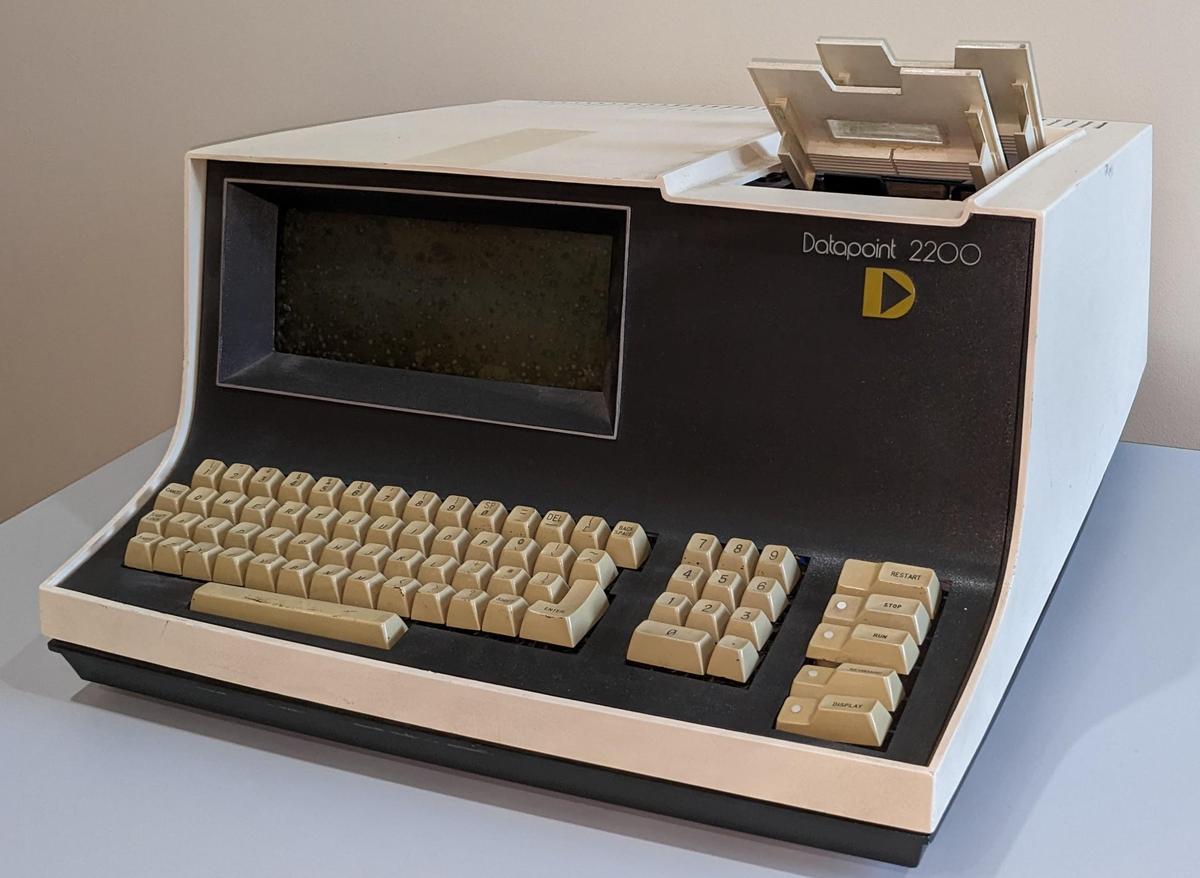
The HLT instruction in the 8086, like many other features, derives from the Datapoint 2200, and there's an interesting story behind that. The Datapoint 2200 was a desktop computer announced in 1970, and sold as a "programmable terminal". The processor of the Datapoint 2200 was implemented with a board of TTL integrated circuits, since this was before microprocessors. The Datapoint manufacturer talked to Intel and Texas Instruments about replacing the board of chips with a single processor chip. Texas Instruments produced the TMX 1795 microprocessor chip and Intel produced the 8008 shortly after,8 both copying the Datapoint 2200's architecture and instruction set. Datapoint didn't like the performance of these chips and decided to stick with a TTL-based processor. Texas Instruments couldn't find a customer for the TMX 1795 and abandoned it. Intel, on the other hand, sold the 8008 as an 8-bit microprocessor, creating the microprocessor market in the process. Intel improved the 8008 to create the popular 8080 microprocessor (1974). Zilog produced the more powerful Z80 (1976), backward-compatible with the 8080.
Intel started designing the iAPX 432 in 1975 to be their high-end 32-bit processor, a "micromainframe" that supported garbage collection and objects in the processor. The iAPX 432 was too complex for the time and as the schedule slipped, Intel decided to produce a stopgap 16-bit processor to compete with Zilog and Motorola: this processor became the 8086. To make it easier for Intel customers to move to the 8086, the processor was designed for compatibility with 8080 assembly language so it inherited much of the architecture and instruction set, although extended from 8 bits to 16 bits.9
The consequence of this history is that the 8086 inherited many features from the Datapoint 2200. The Datapoint 2200 used cheaper shift-register memory so it had a serial processor that operated on one bit at a time. This required the Datapoint 2200 to be little-endian, a feature that lives on in the x86 architecture. Since the Datapoint 2200 was marketed as a programmable terminal, it had parity calculation built into the hardware. Thus, the 8008 and descendants have a parity flag, in contrast to contemporary processors such as the 6800 and 6502 that omitted this moderately complex feature. The use of I/O ports instead of memory-mapped I/O is another feature of the Datapoint 2200 that persists in the x86, but was not used in the 6800 and 6502 and their descendants. The opcodes of the Datapoint 2200 were based on octal 3-bit fields for hardware reasons. The x86 instructions are still designed around octal, but the usual hexadecimal display obscures their structure. Finally, the Datapoint 2200's HALT instruction was exactly copied by the 800810 and persists in x86.
Conclusions
The HLT instruction seems like a simple function, but its implementation touches many parts of the 8086. It is implemented in logic circuitry, completely bypassing the microcode. The implementation became more complicated because of the 8086's four-step bus protocol, as well as interaction between halting and the bus hold feature. This illustrates how complexity creates more complexity, something the RISC processors of the 1980s tried to counter.
I've written multiple posts on the 8086 so far and plan to continue reverse-engineering the 8086 die so follow me on Twitter @kenshirriff or RSS for updates. I've also started experimenting with Mastodon recently as @oldbytes.space@kenshirriff. Thanks to monocasa for suggesting this topic.
Notes and references
-
The instructions implemented outside microcode are the segment register prefixes (ES:, CS:, SS:, DS:), the other prefixes (LOCK, REPNZ, REPZ), the simple flag instructions (CMC, CLC, STC, CLI, STI, CLD, STD), and HLT. These instructions are indicated by the 1BL (one-byte logic) output from the Group Decode ROM. ↩
-
The bus cycle may also include optional Tw wait states after T3 for slow memory. The memory (or I/O device) lowers the READY pin until it is ready to proceed and the Bus Interface Unit waits. I'm ignoring Tw states in this discussion to keep things simpler. ↩
-
For some reason, the T-state flip-flops all hold inverted signals, so strictly speaking a 0 bit goes through the flip-flops. ↩
-
The 8086 has a separate prioritized "request/grant" way for a device to obtain a bus hold, but it doesn't change the underlying hold behavior. ↩
-
During a HALT, the 8086 is not actively using the bus, but it does not release the bus either; it is still electrically driving the bus. Otherwise, the bus would float to random voltages, confusing attached memory chips or other circuitry. ↩
-
When the Bus Interface Unit is unhalted due to an interrupt, you might expect it to immediately start prefetching, accessing unwanted instructions. It turns out that the prefetch circuitry does try to start prefetching and reaches the internal T0 bus state. But it then gets preempted by the interrupt handler microcode, which uses the bus to send two interrupt acknowledge cycles. Immediately after, the microcode routine suspends prefetching. Thus, prefetching doesn't run until the interrupt microcode finishes and reenables prefetching. There's a lot of tricky timing in the 8086 to make everything work. ↩
-
For more history of the stop instruction, see "Computer Architecture", Blaauw and Brooks, page 349. (This the same Brooks who wrote "The Mythical Man-Month" and "No Silver Bullet".) ↩
-
You might wonder how the Intel 4004 fits into this history. Although many of the same people worked on both chips, they have completely different architectures. The 8008 is not at all an 8-bit version of the 4-bit 4004. ↩
-
Assembly code for the 8-bit 8080 processor couldn't run directly on the 16-bit 8086. Instead, a translation program converted the 8080 assembly language to be compatible with the 8086, making some changes in the process. The 8086 dropped some of the less-useful instructions of the 8080, replacing them with multiple instructions in the translation. For instance, the 8080 had conditional subroutine call and return instructions (inherited from the Datapoint 2200), but the 8086 dropped them. ↩
-
To see that the 8008 copied the Datapoint 2200's HALT instruction, note that the Datapoint had three opcodes for HALT (00, 01, and FF), which is a bit unusual. The 8008 also has three opcodes for HLT: 00, 01, and FF. Most instructions in the 8008 used the same opcode values as the Datapoint, with a few minor changes. ↩


The 432 itself might be worth decapping and examining--as a final post mortem of a fiasco.
ReplyDeleteThe 432 was as least two chips, not one. They were tied together by only a 16-pin bus, despite supposedly being 32-bit. You'd have no clues to identify registers: Intel kept the assembly language secret (rumored to be stack-based), only allowing a proprietary Ada compiler. I bet the circuits juggling its 64K "objects" protection had influence on the 64K selector protection of the 286. And so on...
The HLT instruction was used ina technique for generating audio by pulse-width modulation on the IBM PC. The CPU would respond to a timer interrupt, fetch the next audio sample from memory and write it to an I/O port that controls another timer channel attached to the speaker, programmed as a one-shot timer. It was not fast enough for luxuries like saving and restoring registers or actually returning from the interrupt handler. The code just set the interrupt flag, reset SP and issued a HLT instruction to wait for the next sample interval. I’m HLT mode the interrupt response time was minimal and constant, preventing jitter that would otherwise degrade the audio quality.
ReplyDeleteAt first I thought that an infinite loop in the microcode (probably checking for interrupt conditions to see if it should break) would be enough to implement halt (maybe turn off prefetch first too), but that wouldn't get you the special bus cycle. I guess that the bus handling is where most of the complexity in the halt instruction lies.
ReplyDeleteAnother fascinating article - thank you! Though it doesn't clear up one mystery around HLT that I was hoping it would. Have a look at the following two trace dumps taken from an IBM 5160 XT which contains an Intel 8088:
ReplyDeletehttps://www.reenigne.org/misc/F4_0.txt
https://www.reenigne.org/misc/F4_1.txt
They differ in that in F4_1.txt a NOP is executed immediately before HLT, whereas in F4_0.txt before the HLT executes the prefetch queue is full.
The output from the programmable interval timer goes low on line 370 in both files (the "D" in column 29 changes to a "C") which triggers an interrupt signal ("I" in column 30) to the CPU on line 374. The status lines showing the type of IO (column 8) go from "p" (passive) to "A" (interrupt acknowledge) on line 379 in F4_0.txt and line 380 in F4_1.txt. What bit of state in the CPU is different while the CPU is halted in these two cases, and why does it cause this extra delay? It seems to be related to state of the bus when HLT is started: I've been able to predict it accurately with the logic on this line: https://github.com/reenigne/reenigne/blob/6ee16df0d974ff41e8591294b9349701fc01233d/8088/xtce/xtce_microcode.h#L2522 .
It may be something that happens with hardware interrupt requests in general - I haven't experimented with them yet except in HLT and WAIT. It doesn't seem to happen during WAIT, probably because when interrupt request occurs during execution of WAIT then it's handled explicitly by the microcode (using the INT condition), not by overriding the queue-unavailable signal. So the timing of the interrupt sequence is completely determined by the microcode program there. It's curious that it "leaks through" the HLT state though.