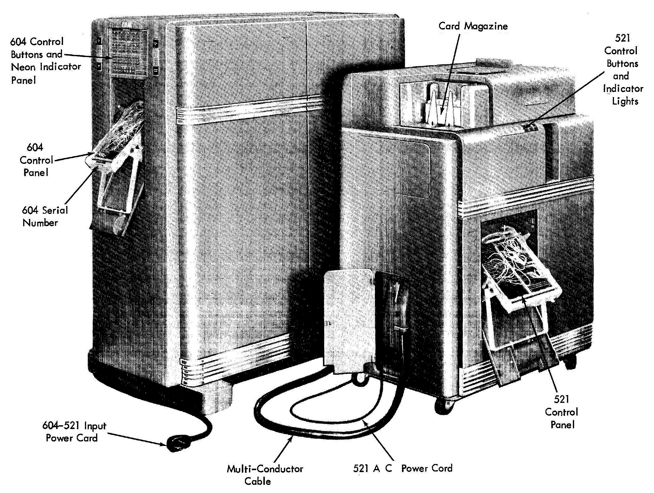
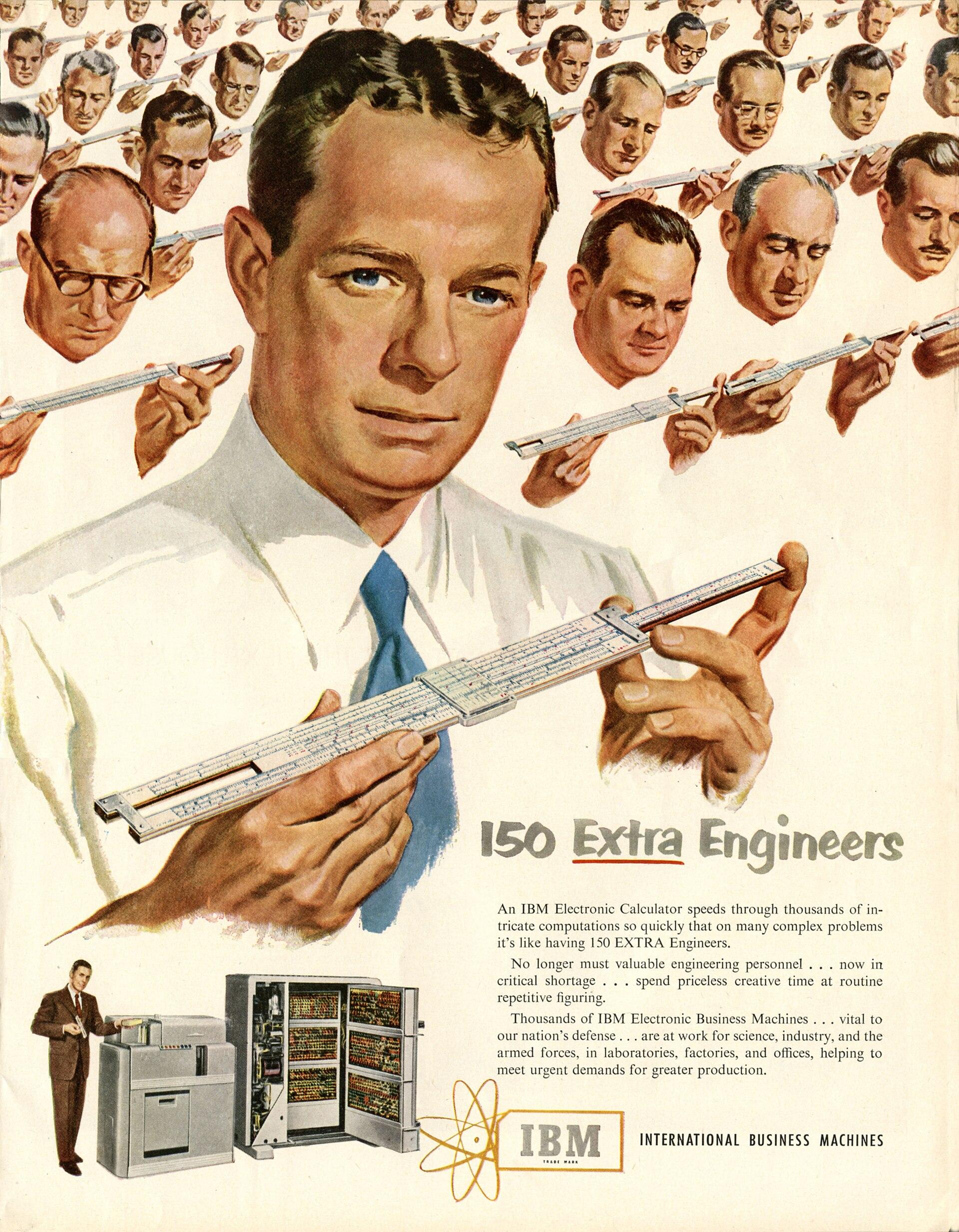
In 1948, IBM introduced the 604 Electronic Calculating Punch. This machine was a programmable calculator, about the size of a double refrigerator. It was not quite a computer, but was programmed by plugging wires into a plugboard. This machine read numbers from a punch card, performed up to 60 calculations on these numbers, and then recorded the results by punching holes in the card.1 It processed 100 cards per minute—over one card per second—and IBM advertised it as the equivalent of 150 engineers. The machine rented for $550 a month, making it very popular, with over 5600 units produced.2
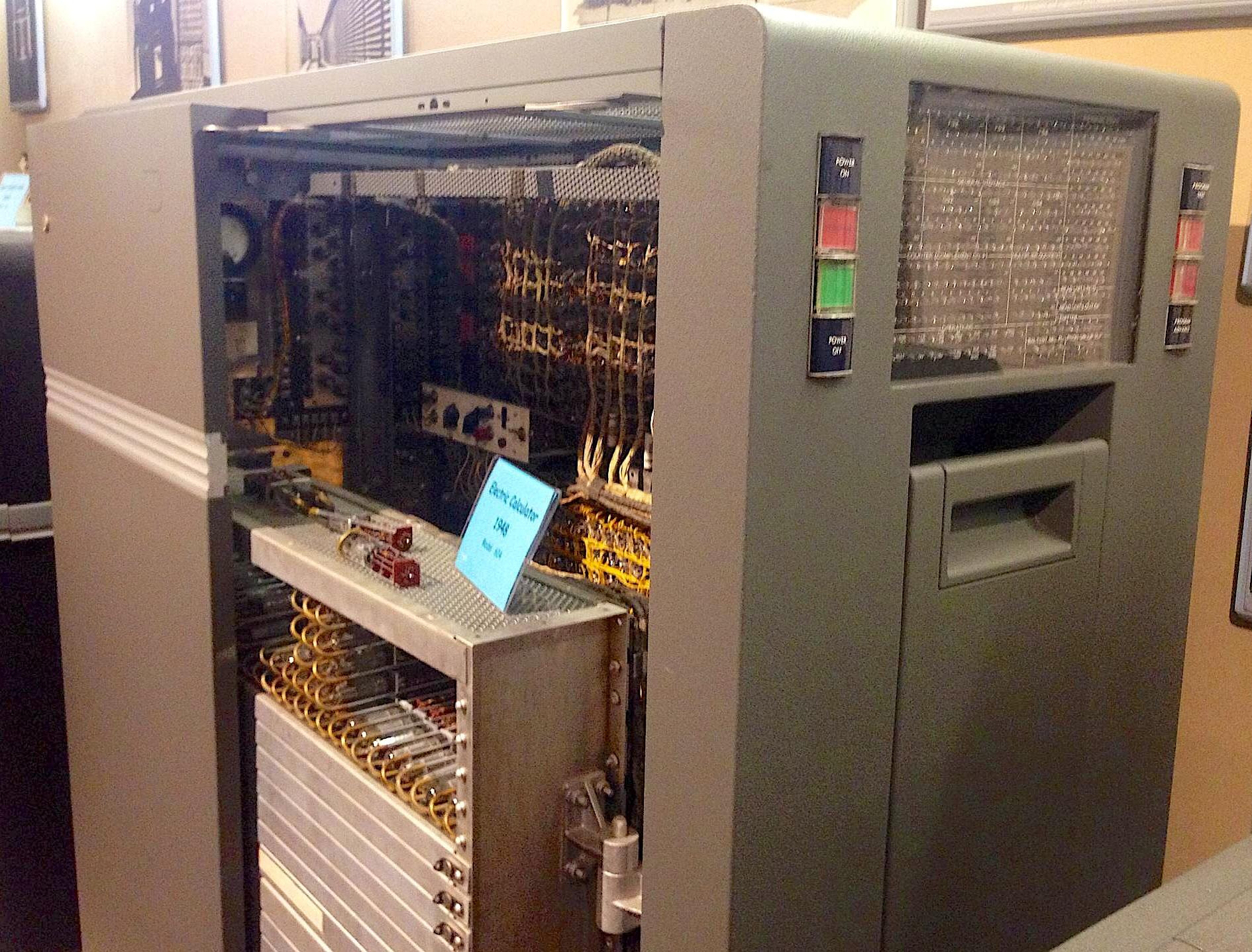
The IBM 604 came out just after the transistor was invented, too early to use transistors. At the time, calculators and computers were moving from slow electromechanical components to fast vacuum tubes. One of the innovations of the 604 was to combine a vacuum tube and its associated circuitry into a pluggable module. Along the left side of the photo above, you can see rows of these modules with the handles sticking out, making it easy to replace a faulty module. More modules are behind the silver metal covers. In total, the IBM 604 used about 1300 vacuum tubes.
The photo below shows a pluggable tube module, with a vacuum tube underneath the insulated handle. The nine pins at the bottom of the module plugged into a socket in the 604, with the sockets connected by backplane wiring. The vacuum tube was also socketed, so a bad tube could be quickly replaced. At the left, the resistors and capacitors are mounted on insulating wafers. Modules provided a dense way to implement circuits, packing components into three dimensions.
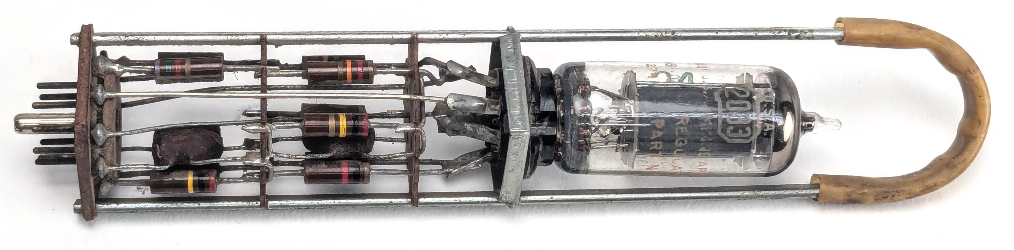
Each pluggable tube module implemented a specific function, such as an inverter, amplifier, or power driver. The module above is a "trigger" module, type TR-3. A trigger is a circuit with two states—on and off—and can be switched from one state to the other, providing one bit of temporary storage. (In modern terminology, this is called a flip-flop.) Triggers were important building blocks in the 604, generating timing signals and storing pulses. Arithmetic in the IBM 604 was implemented with decimal counters, built from TR3 triggers.
In this article, I describe the circuitry of the TR-3 trigger module. (I recently wrote about a thyratron module in the 604; this is a different module.) After reverse-engineering the module, I powered it up. The video above shows the module in operation. By pressing buttons, I switch the trigger from one state to the other. Glowing orange neon bulbs show the state of the trigger module. The fundamental feature of the trigger is that it stays in a state until I push the other button. This might appear trivial, but the ability to store information is vitally important for computation.
How a vacuum tube works
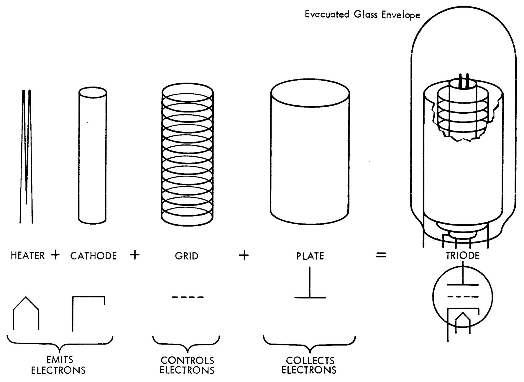
The trigger module uses a common type of vacuum tube called a triode, which amplifies a weak signal to control a stronger signal. The diagram below shows the construction of a triode vacuum tube. The heater is a filament, similar to an incandescent light bulb, that heats the cathode to roughly 750 ºC. At this high temperature, the cathode emits electrons. If a large positive voltage (say, 150 volts) is put on the plate, the negatively charged electrons are attracted to the plate. The stream of electrons from the cathode to the plate causes a current to flow through the tube. Since air would block the electrons, the fragile glass envelope holds a vacuum, giving the vacuum tube its name. The current is controlled by the grid: if a small negative voltage is placed on the grid, it repels the negative electrons, preventing them from reaching the plate and blocking the current through the tube.3 Thus, a small signal on the grid controls the large current through the tube.
The advantage of vacuum tubes was that they could switch on and off millions of times per second, phenomenally faster than electromechanical devices such as relays. The clock speed of the IBM 604 was 50 kilohertz, much below what a tube could handle, but three orders of magnitude faster than the 50 hertz pulses in an electromechanical accounting machine like the contemporaneous IBM 407.
The tube that I used in the module is called a 2033.6 This tube is a dual triode, combining two triodes into one physical glass tube. Dual triodes were very popular because they doubled the density of the circuitry. In the photo below, the two vertical black structures are the plates of the two triodes; the other structures are not visible as they are inside the plates.
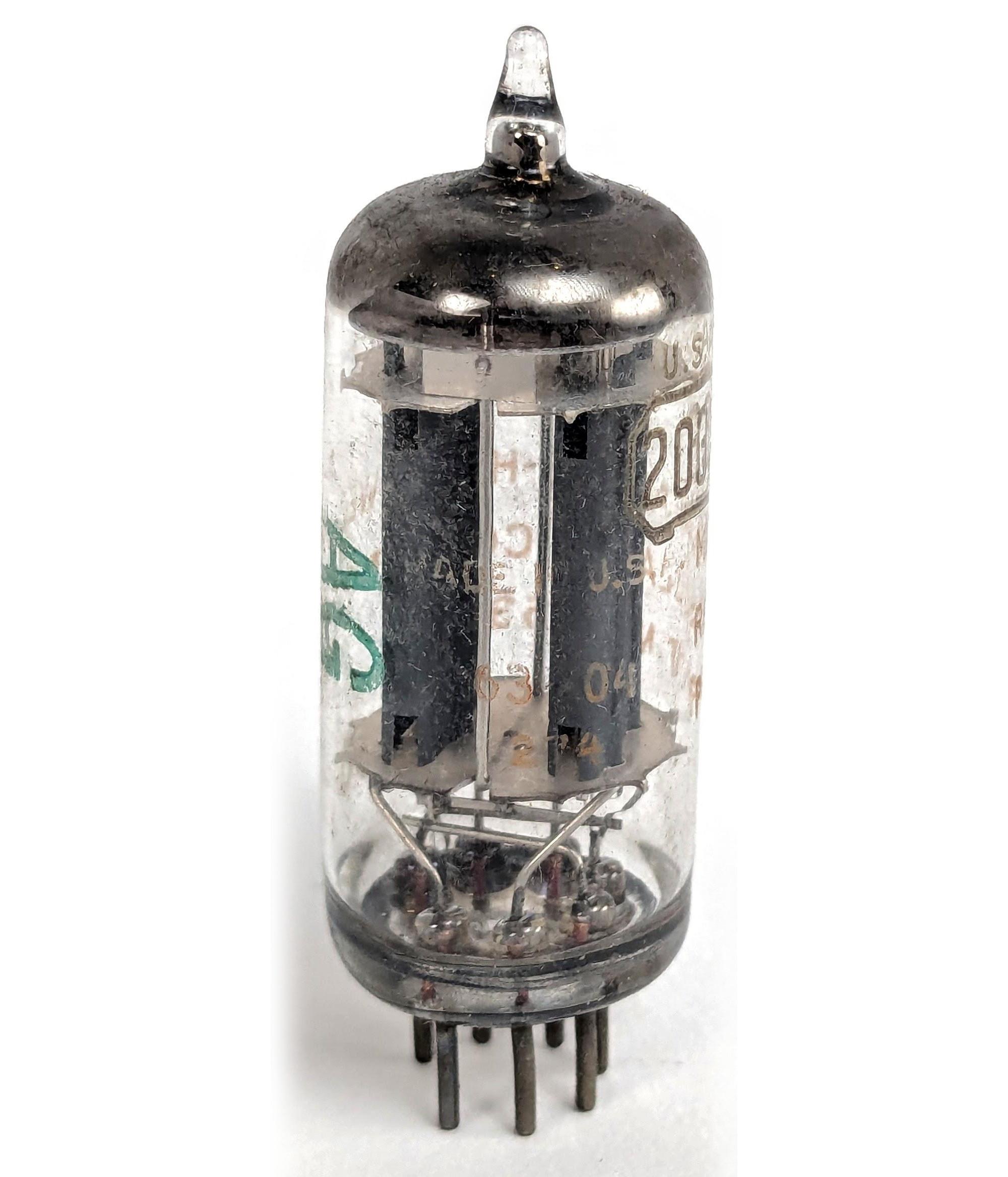
This tube is a "miniature" vacuum tube, about 5 cm long including the seven pins at the bottom of the glass envelope.4 Since a single triode has five connections, you might wonder how a dual triode manages with seven pins instead of 10. The trick is that both triodes share the cathode and heater connections, which limits the tube to applications that don't require separate cathodes.
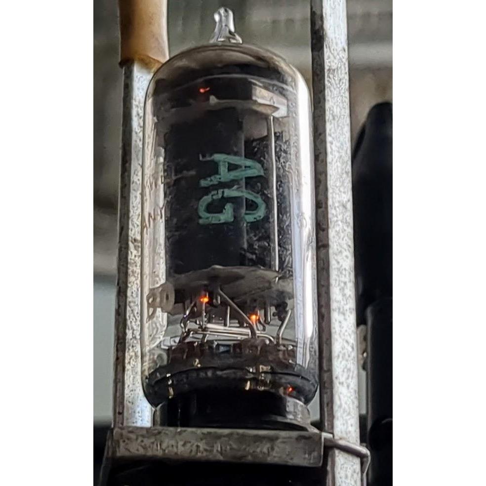
One disadvantage of vacuum tubes is that the heater uses considerable power. This tube's heater requires 6.3 volts at 300 milliamps—almost 2 watts per tube. Using 6.3 volts may seem a bit random, but many vacuum tubes used this voltage for historical reasons: this was the typical voltage provided by a 6-volt automobile battery.5 In the photo below, you can see the orange glow from the two heaters, mostly hidden by the plates but visible at the top and bottom.
Inverters and the trigger circuit
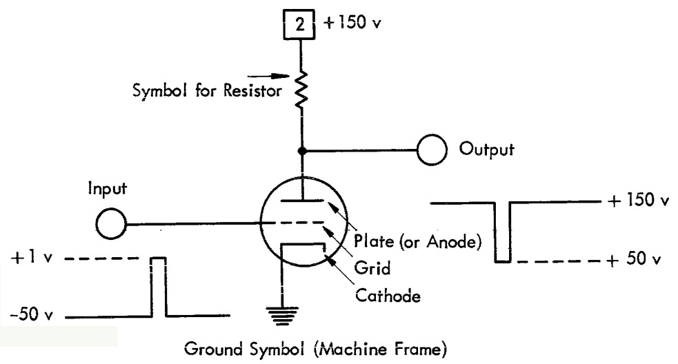
The trigger circuit is based on two inverters, so I'll start by explaining the tube inverter circuit.7 The idea of an inverter is to amplify and invert the input signal: a "low" input results in a "high" output and vice versa. First, consider a low input: if a negative voltage is applied to the grid, the flow of electrons is blocked, turning off the tube. In this case, the resistor pulls the output high with 150 volts. However, if a positive voltage is applied to the grid, the tube turns on and conducts current. This current pulls the output down, due to the voltage drop across the resistor, producing a low output of 50 volts. Thus, a low input causes a high (150 V) output, while a high input causes a low (50 V) output, providing the desired inverter action. Note that the input signal has a swing of over 50 volts, very large compared to a transistor circuit. Moreover, the output voltages are much higher than the input voltages, which is somewhat inconvenient when connecting circuits.
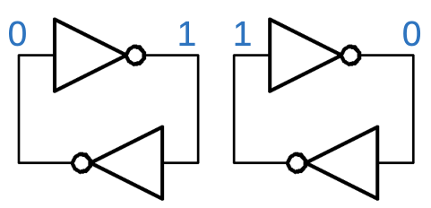
A trigger is constructed from two inverters connected in a loop. The output of the first inverter is fed into the second inverter, and the output of the second inverter is looped back to the first inverter. If the first inverter has a high output, the second inverter has a low output, which is fed back to the first, maintaining the high output from the first inverter. The situation is similar but opposite if the first inverter has a low output. Thus, this circuit has two stable states, with one inverter on and the other off.8 Once the circuit is placed into a state, it will remain in that state until forced into the other state.
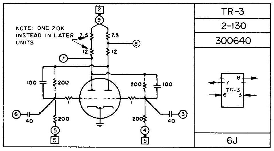
I reverse-engineered the TR-3 module, creating the schematic below.9 It's a bit tricky to see the loop of inverters because the two inverters share one tube and are wired in a cross-coupled arrangement. In brief, one inverter uses the left half of the tube and the other uses the right half. The plate output from one side is wired to the grid input on the other side, through 200K and 1K resistors. The two module outputs (pins 7 and 8) are taken from the plates, but output 8 has a resistor between it and the plate. As a result, the two outputs provide different voltage levels, making the module more flexible to use.10 The two inputs force the trigger into one state or the other. The inputs are connected through 40 pF capacitors, providing AC coupling so the inputs can use different voltage levels from the outputs.
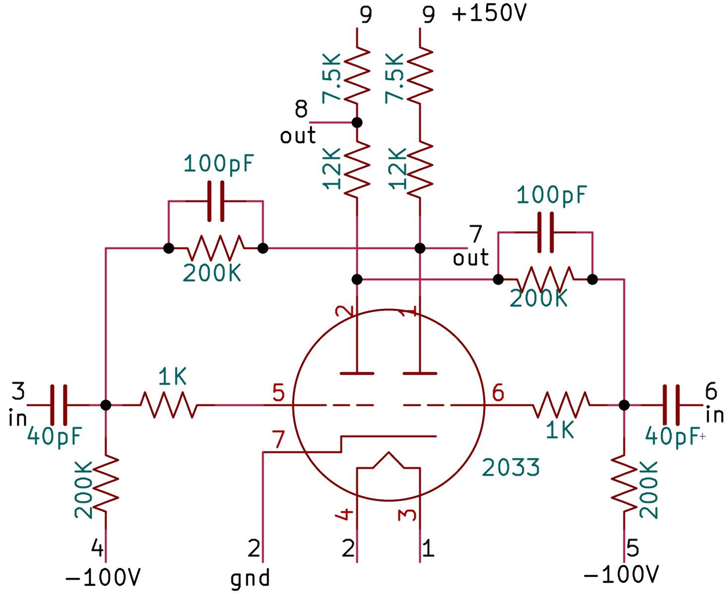
One tricky part is the connection between one inverter's output and the other inverter's input. The problem is that the output voltage is 50 to 150 volts, but the input grid voltage must be close to zero (a bit positive or a bit negative). The solution is to use a large negative voltage (-100 volts) and a resistor divider as a level shifter. With a large positive voltage from the plate and a large negative bias voltage, the resulting grid voltage ends up being moderately positive or moderately negative. As a result, the circuit requires both a high positive voltage (for the plate) and a high negative voltage (for the bias), complicating the power supply requirements.
The inputs are fed into the grid through capacitors, allowing a pulse to pass through the capacitor to the grid. You might expect that a positive pulse would turn on the triode, but the module was used in the opposite way, with a negative pulse to turn off the triode. (This direction is more sensitive, because a tube has more gain when it is on.) Thus, a negative pulse on the left input will turn off the left side. The plate output of the left side goes high, pulling the gate of the right side high, turning the right side on. The plate output from the right side goes low, pulling the gate of the left side low, keeping the left tube off. Similarly, a negative pulse on the right input turns off the right side, causing the left side to turn on. Multiple pulses have no effect; that side remains off. Positive pulses also have no effect; the circuit is designed so a positive pulse is not sufficient to turn a triode on.11
I found the trigger circuit to be somewhat temperamental: the trigger needs to be stable enough to stay in one state or the other, while also unstable enough that an input pulse will reliably flip it to the other state. The circuit depends on carefully balancing the grid voltages and the input voltages. I experimented with different supply voltages and found that in some cases the trigger would oscillate, while in other cases, the trigger would get stuck in one state. Interestingly, the later IBM 650 computer abandoned this type of trigger circuit, instead using diode logic (AND and OR gates) to set and reset a loop of two inverters. With this type of trigger, the state is determined by reliable Boolean logic, rather than analog interactions of changing voltages.
Conclusion
The development of the trigger is an under-appreciated step in the history of digital computers. Because the trigger holds information—state—it can be used to create a state machine. This allows a computer to perform operations step by step, rather than a jumble of actions all happening at the same time.
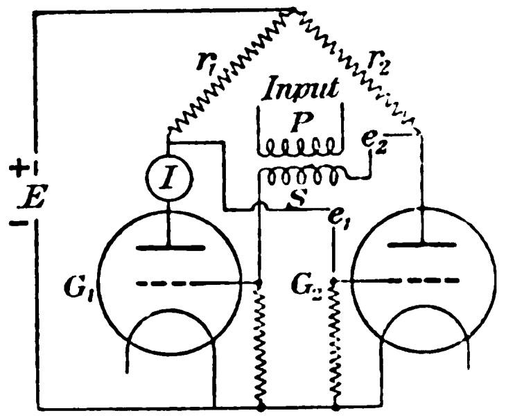
The trigger circuit dates back to 1918, when two British physicists, William Eccles and Frank Jordan, invented a circuit that used two cross-coupled triodes to create a circuit with two stable states. They viewed this circuit as a type of relay, triggered by a small signal and retaining its state until it was reset. They patented the circuit (Improvements in ionic relays) and wrote about it: A Trigger Relay Utilising Three-Electrode Thermionic Vacuum Tubes. (The Eccles-Jordan trigger circuit below is conceptually similar to the TR-3 trigger module, using cross-coupled triodes. One difference is that the input is coupled with a transformer.)
The Eccles-Jordan trigger eventually led to digital counters. In 1939, the journal Electronics published an article Trigger Circuits, describing how trigger circuits could be combined to construct high-speed counters. One problem was that triggers can be easily combined to count in binary, but in the 1940s, calculating and accounting machines generally used decimal numbers, not binary. In the groundbreaking ENIAC computer (1945), bulky counters were constructed by putting ten triggers in a ring to count each decimal digit. IBM engineers invented a more efficient decimal counter that used four triggers instead of ten, coming up with binary-coded decimal (BCD) and obtaining a 1946 patent: Electronic Counting Circuit. IBM used this counting circuit in the 603 Electronic Multiplier (1946), followed by the 604 Electronic Calculating Punch (1948).
Modern computers use triggers—albeit under the modern name "flip-flops"—by the millions, but now they are microscopic transistor circuits instead of vacuum-tube modules.
For updates, follow me on Bluesky (@righto.com), Mastodon (@[email protected]), or RSS. Thanks to Robert Garner for providing the module and to CuriousMarc for hardware support. AI statement: Despite the presence of the em dash, no AI was used in the writing of this article (details).
Notes and references
-
The punch cards were read and punched by a separate unit, the IBM 521 Card Reader/Punch, which was connected to the IBM 604 through a thick cable. The 521 had a card magazine on the upper left to hold cards to be read. After cards were processed, they were collected in the hopper in the middle of the 521. Note the plugboard control panels in both the 604 and the 521.
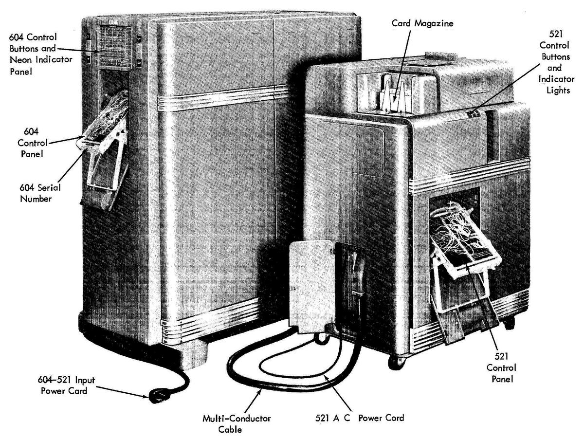 The IBM 521 Card Reader/Punch to the right of the IBM 604 Electronic Calculating Punch. Photo from Customer Engineering Manual of Instruction.
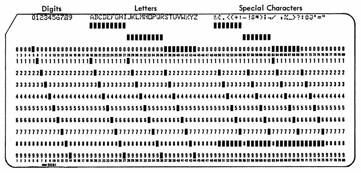
The punch cards were standard IBM 80-column cards, introduced back in 1928. The position of a hole in a column indicated the digit value for that column. For a particular task, the 80 columns would be divided into fields to hold various numbers. The 604 only supported numbers, not other alphanumeric symbols. A negative number was indicated by punching an additional hole over the units digit, using the second row from the top. (This was called an "X-punch", unrelated to the letter X.)
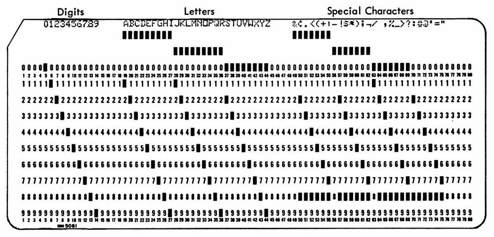 Punch card code, from IBM 29 Card Punch Reference Manual. This code is somewhat later, with a variety of special characters.
 -
An interesting video showing the manufacturing and operation of the IBM 604 is here. For information on the IBM 604, see the Operating Manual. The Customer Engineering Manual of Instruction explains the 604 in detail, showing a TR-3 tube module on page 20. See IBM's Early Computers for information on the development of the 604. ↩
-
You can think of a triode as analogous to an NPN transistor, with the grid as the base, the plate as the collector, and the cathode as the emitter. ↩
-
The IBM 604 also used dual-triode vacuum tubes with nine pins, rather than seven, such as the type 5965. (Seven and nine pins were standard sizes for tubes.) The nine-pin tubes had separate connections for each cathode; this allowed the tubes to be used in circuits such as "cathode followers". The two filaments were in series, sharing a common "middle" pin, which is why the tube used nine pins instead of 10. ↩
-
For a discussion of filament voltages, see Valves, 1939. This article discusses how car radios motivated the use of 6.3 volt filaments in the United States, where 6-volt car batteries were common. ↩
-
The 2033 tube is very similar to the popular 6J6 tube, but optimized for computer circuits. The IBM 1684 tube is also very similar. The tube module that I examined was missing its tube, so I can't guarantee that the 2033 is the correct tube. ↩
-
The standardized tube modules weren't as standardized as one might expect. For instance, the 604 used 27 different types of inverter modules in total. For a detailed discussion of the tube inverter, see IBM 604 CE Manual, pages 26-41. ↩
-
A trigger circuit is symmetrical, so how do you define whether a trigger circuit is on or off? IBM's convention was that if the left triode was conducting, the trigger was on, while if the right triode was conducting, the trigger was off. See IBM 604 CE Manual, page 54. ↩
-
The 604 manual includes a schematic of the TR-3 module (and other modules). Inconveniently, I didn't find this schematic until I had reverse-engineered the module; I made minor adjustments to my schematic based on this. This schematic is a bit tricky to interpret. All the resistances are in thousands of ohms (e.g. 1 is 1 KΩ), and capacitances are in "micromicrofarads" (i.e. pF). The circled numbers indicate pins of the module, while numbers in square boxes indicate voltages according to an obscure standard: 2 is +150V, and 5 is -100 V. "2-110" and "300638" are IBM part numbers. "6J" indicates that the tube is in the 6J family, where 6 indicates the heater voltage and J indicates a triode. The 604 documentation used cryptic boxes as symbols for the modules, with the arrows indicating the inputs and outputs; note that output 7 is at a lower position than output 8, indicating a lower voltage level.
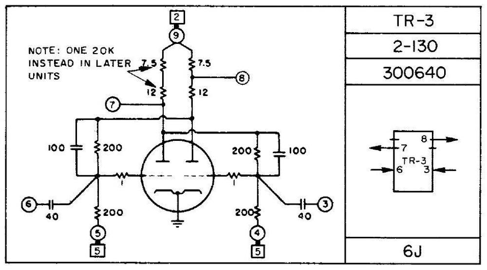 Schematic from the CE Manual of Instruction, page 260.
 -
The two outputs from the trigger module are at different voltage levels. The idea is that a circuit could use either output, depending on which voltage level was more convenient. The asymmetrical outputs caused me great trouble, however, since I wanted to attach neon bulb indicators to show the state of both outputs. I had to carefully adjust the voltages so that the bulbs had enough voltage in the "on" state to turn on, but also a sufficiently low voltage in the "off" state to turn off. (When a neon bulb turns on, the neon gas ionizes, so it requires a significantly lower voltage to turn the bulb off.)
The IBM 604 used neon bulbs to show the state of various circuits, both in the front panel and internally. However, unlike me, IBM used a single bulb for each trigger, either on or off, so the inconsistent voltage levels didn't cause problems. ↩
-
The 604 used 12 different types of trigger modules, from TR-1 through TR-42. The different trigger circuits were similar, but had different component values to tune the characteristics, as well as different resistors for the output levels. A few types used resistive inputs instead of capacitively coupled inputs.
The trigger modules were used in a variety of different ways. Briefly removing the negative bias from one side would turn that side on; this was used for reset circuits. Second, a plate could be pulled low, turning off the tube on the other side. Third, the input could be connected directly to the input, rather than going through a capacitor, with a negative voltage turning the triode off and a positive voltage turning the triode on. Other triggers used a capacitor between the plate and grid on each side to filter out noise and contact bounce. Some triggers used capacitor inputs (as in the module I described), but fed the same negative input pulse to both sides. The pulse is ignored by the triode that is on, but flips the triode that is off. The result is that the trigger switches state on each pulse—analogous to a toggle flip-flop—and divides the input pulses by two. ↩