In 1979, Intel introduced the 8088 microprocessor, a variant of the 16-bit 8086 processor. IBM's decision to use the 8088 processor in the IBM PC (1981) was a critical point in computer history, leading to the success of the x86 architecture. The designers of the IBM PC selected the 8088 for multiple reasons, but a key factor was that the 8088 processor's 8-bit bus was similar to the bus of the 8085 processor.1 The designers were familiar with the 8085 since they had selected it for the IBM System/23 Datamaster, a now-forgotten desktop computer, making the more-powerful 8088 processor an easy choice for the IBM PC.
The 8088 processor communicates over the bus with memory and I/O devices through a highly-structured sequence of steps called "T-states." A typical 8088 bus cycle consists of four T-states, with one T-state per clock cycle. Although a four-step bus cycle may sound straightforward, its implementation uses a complicated state machine making it one of the most difficult parts of the 8088 to explain. First, the 8088 has many special cases that complicate the bus cycle. Moreover, the bus cycle is really six steps, with two undocumented "extra" steps to make bus operations more efficient. Finally, the complexity of the bus cycle is largely arbitrary, a consequence of Intel's attempts to make the 8088's bus backward-compatible with the earlier 8080 and 8085 processors. However, investigating the bus cycle circuitry in detail provides insight into the timing of the processor's instructions. In addition, this circuitry illustrates the tradeoffs and implementation decisions that are necessary in a production processor. In this blog post, I look in detail at the circuitry that implements this state machine.
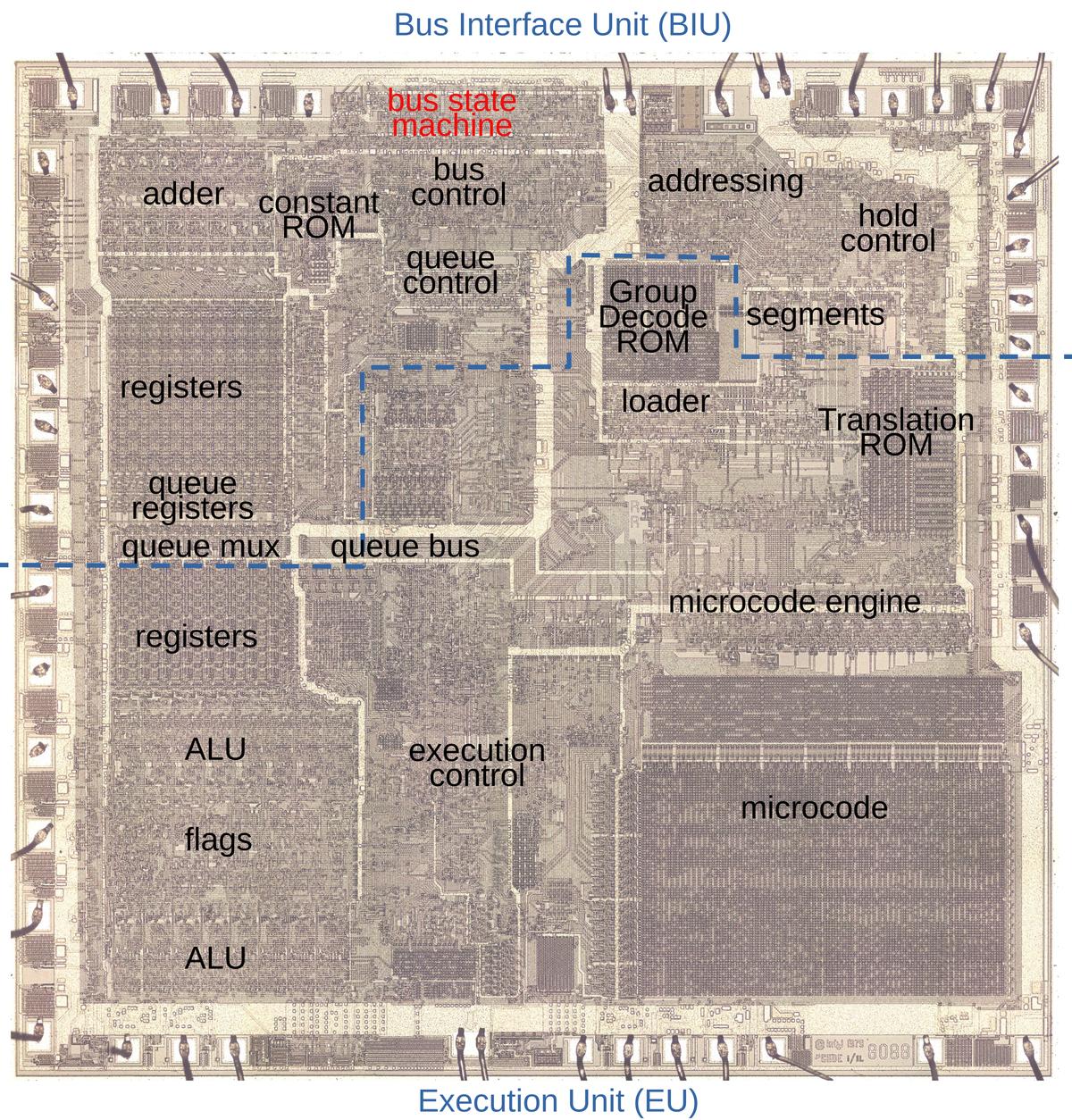
By examining the die of the 8088 microprocessor, I could reverse engineer the bus circuitry. The die photo below shows the 8088 microprocessor's silicon die under a microscope. Most visible in the photo is the metal layer on top of the chip, with the silicon and polysilicon mostly hidden underneath. Around the edges of the die, bond wires connect pads to the chip's 40 external pins. Architecturally, the chip is partitioned into a Bus Interface Unit (BIU) at the top and an Execution Unit (EU) below, with the two units running largely independently. The BIU handles bus communication (memory and I/O accesses), while the Execution Unit (EU) executes instructions. In the diagram, I've labeled the processor's key functional blocks. This article focuses on the bus state machine, highlighted in red, but other parts of the Bus Interface Unit will also play a role.
Although I'm focusing on the 8088 processor in this blog post, the 8086 is mostly the same. The 8086 and 8088 processors present the same 16-bit architecture to the programmer. The key difference is that the 8088 has an 8-bit data bus for communication with memory and I/O, rather than the 16-bit bus of the 8086. For the most part, the 8086 and 8088 are very similar internally, apart from trivial but numerous layout changes on the die. In this article, I'm focusing on the 8088 processor, but most of the description applies to the 8086 as well. Instead of constantly saying "8086/8088", I'll refer to the 8088 and try to point out places where the 8086 is different.
The bus cycle
In this section, I'll describe the basic four-step bus cycles that the 8088 performs.2
To start, the diagram below shows the states for a write cycle (slightly simplified3), when the 8088 writes to memory or an I/O device.
The external bus activity is organized as four "T-states", each one clock cycle long and called T1, T2, T3, and T4, with
specific actions during each state.
During T1, the 8088 outputs the address on the pins. During the T2, T3, and T4 states, the 8088 outputs the data word on the same pins.
The external memory or I/O device uses the T states to know when it is receiving address information or data over the bus lines.
For a read, the bus cycle is slightly different from the write cycle, but uses the same four T-states.
During T1, the address is provided on the pins, the same as for a write.
After that, however, the processor's data pins are "tri-stated" so they float electrically, allowing the external memory to put data on the bus.
The processor reads the data at the end of the T3 state.
The purpose of the bus state machine is to move through these four T states for a read or a write. This process may seem straightforward, but (as is usually the case with the 8088) many complications make this process anything but easy. In the next sections, I'll discuss these complications. After that, I'll explain the state machine circuitry with a schematic.
Address calculation
One of the notable (if not hated) features of the 8088 processor is segmentation: the processor supports 1 megabyte of memory, but memory is partitioned into segments of 64 KB for compatibility with the earlier 8080 and 8085 processors. The 8088 calculates each 20-bit memory address by adding the value of a segment register to a 16-bit offset. This calculation is done by a dedicated address adder in the Bus Interface Unit, completely separate from the chip's ALU. (This address adder can be spotted in the upper left of the earlier die photo.)
Calculating the memory address complicates the bus cycle. As the timing diagrams above show, the processor issues the memory address during state T1 of the bus cycle.
However, it takes time to perform the address calculation addition, so the address calculation must take place
before T1.
To accomplish this, there are two "invisible" bus states before T1; I call these states "TS" (T-start) and "T0".
During these states, the Bus Interface Unit uses the address adder to compute the address, so the address will be available
during the T1 state.
These states are invisible to the external circuitry because they don't affect the signals from the chip.
Thus, a single memory operation takes six clock cycles: two preparatory cycles to compute the address before the four visible cycles.
However, if multiple memory operations are performed, the operations are overlapped to achieve a degree of pipelining that improves performance.
Specifically, the address calculation for the next memory operation takes place during the last two clock cycles of the current
memory operation, saving two clock cycles.
That is, for consecutive bus cycles, T3 and T4 of one bus cycle overlap with TS and T0 of the next cycle.
In other words, during T3 and T4 of one bus cycle, the memory address gets computed for the next bus cycle.
This pipelining significantly improves the performance of the 8088, compared to taking 6 clock cycles for each bus cycle.
With this timing, the address adder is free during cycles T1 and T2.
To improve performance in another way, the 8088 uses the adder during this idle time to increment or decrement memory addresses.
For instance, after popping a word from the stack, the stack pointer needs to be incremented by 2.5
Another case is block move operations (string operations), which need to increment or decrement the pointers each step.
By using the address adder, the new pointer value is calculated "for free" as part of the memory
cycle, without using the processors regular ALU.4
Address corrections
The address adder is used in one more context: correcting the Instruction Pointer value. Conceptually, the Instruction Pointer (or Program Counter) register points to the next instruction to execute. However, since the 8088 prefetches instructions, the Instruction Pointer indicates the next instruction to be fetched. Thus, the Instruction Pointer typically runs ahead of the "real" value. For the most part, this doesn't matter. This discrepancy becomes an issue, though, for a subroutine call, which needs to push the return address. It is also an issue for a relative branch, which jumps to an address relative to the current execution position.
To support instructions that need the next instruction address, the 8088 implements a micro-instruction CORR, which corrects the Instruction Pointer.
This micro-instruction subtracts the length of the prefetch queue from the Instruction Pointer to determine the "real" Instruction Pointer.
This subtraction is performed by the address adder, using correction constants that are stored in a small Constant ROM.
The tricky part is ensuring that using the address adder for correction doesn't conflict with other uses of the adder.
The solution is to run a special shortened memory cycle—just the
TS and T0 states—while the CORR micro-instruction is performed.6
These states block a regular memory cycle from starting, preventing a conflict over the address adder.
Prefetching
The 8088 prefetches instructions before they are needed, loading instructions from memory into a 4-byte prefetch queue.
Prefetching usually improves performance, but can result in an
instruction's memory access being delayed by a prefetch, hurting overall performance.
To minimize this delay, a bus request from an instruction will preempt a prefetch, even if the prefetch has
gone through TS and T0.
At that point, the prefetch hasn't created any bus activity yet (which first happens in T1), so preempting the prefetch
can be done cleanly.
To preempt the prefetch, the bus cycle state machine jumps back to TS, skipping over T1 through T4, and starting the desired access.
A prefetch will also be preempted by the micro-instruction that stops prefetching (SUSP) or the micro-instruction
that corrects addresses (CORR). In these cases, there is no point in completing the prefetch, so the state machine cycle
will end with T0.
Wait states
One problem with memory accesses is that the memory may be slower than the system's clock speed, a characteristic of less-expensive
memory chips.
The solution in the 1970s was "wait states".
If the memory couldn't respond fast enough, it would tell the processor to add idle clock cycles called wait states, until
the memory could respond.7
To produce a wait state, the memory (or I/O device) lowers the processor's READY pin until it is ready to proceed.
During this time, the Bus Interface Unit waits, although the Execution Unit continues operation if possible.
Although Intel's documentation gives the wait cycle a separate name (Tw), internally the wait is implemented by repeating the T3 state as long as the READY pin is not active.
Halts
Another complication is that the 8088 has a HALT instruction that halts program execution until an interrupt comes in.
One consequence is that HALT stops bus operations (specifically prefetching, since stopping execution will automatically stop instruction-driven bus operations).
A complication is that the 8088 indicates the HALT state to external devices by performing a special T1 bus cycle
without any following bus cycles.
But wait: there's another complication. External devices can take control of the bus through the HOLD functionality,
allowing external devices to perform operations such as DMA (Direct Memory Access).
When the device ends the HOLD, the 8088 performs another special T1
bus cycle, indicating that the HALT is still in effect.
Thus, the bus state machine must generate these special T1 states based on HALT and HOLD actions.
(I discussed the HALT process in detail here.)
Putting it all together: the state diagram
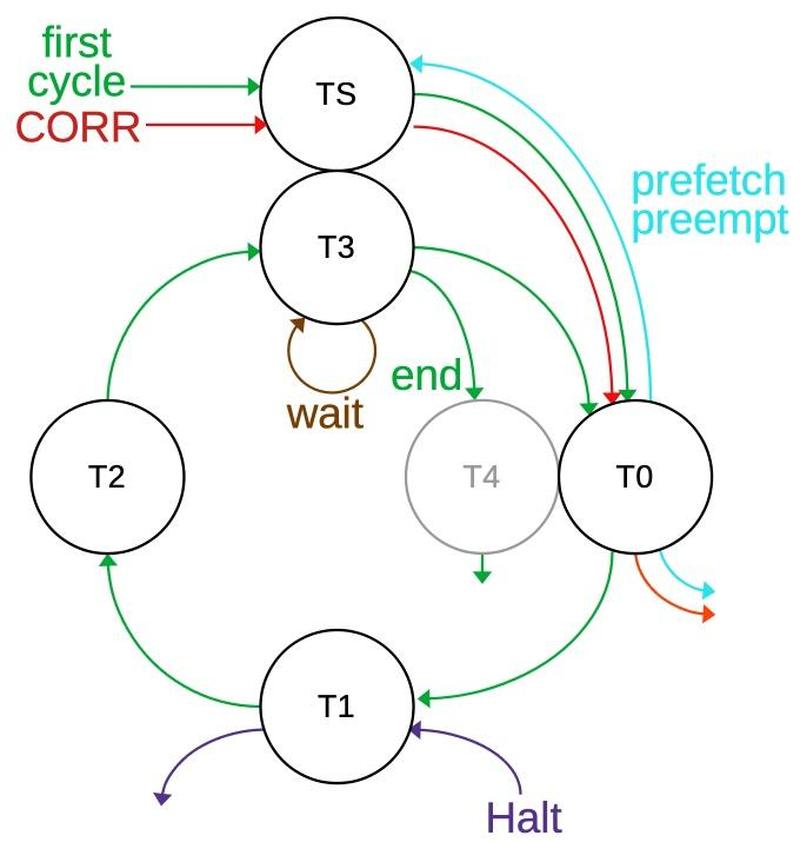
The state diagram below summarizes the different types of bus cycles.
Each circle indicates a specific T-state, and the arrows indicate the transitions between states.
The green line shows the basic bus cycle or cycles, starting in TS and then going around the cycle.
From T3, a new cycle can start with T0 or the cycle will end with T4.
Thus, new cycles can start every four clocks, but a full cycle takes six states (counting the "invisible" TS and T0).
The brown line shows that the bus cycle will stay in T3 as long as there is a wait state.
The red line shows the two cycles for a CORR correction, while the purple line shows the special T1 state for a HALT
instruction.
The cyan line shows that a prefetch cycle can be preempted after T0; the cycle will either restart at TS or end.
I'm showing states TS and T3 together since they overlap but aren't the same.
Likewise, I'm showing T4 and T0 together. T4 is grayed out because it doesn't exist from the state machine's perspective;
the circuitry doesn't take any particular action during T4.
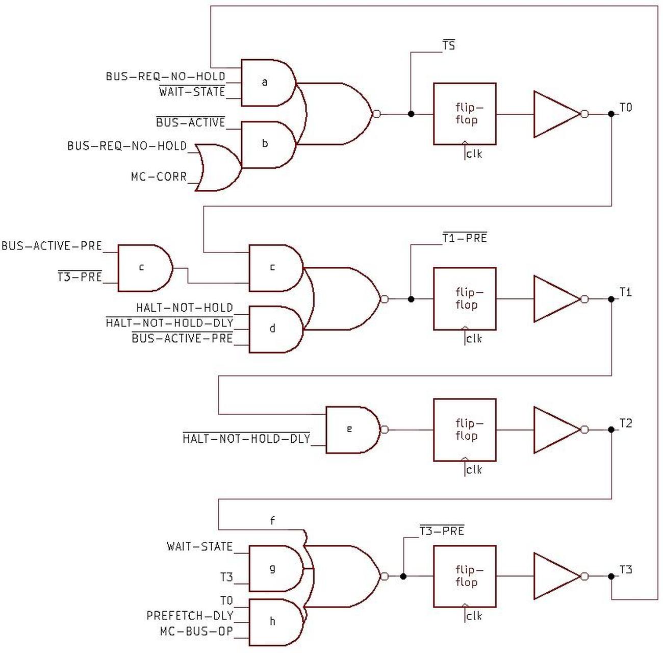
The schematic below shows the implementation of the state machine.
The four flip-flops represent the four states, with one flip-flop active at a time, generating states T0, T1, T2,
and T3 (from top to bottom).
Each output feeds into the logic for the next state, with T3 wrapping back to the top, so the circuit moves through
the states in sequence.
The flip-flops are clocked so the active state will move from one flip-flop to the next according to the system clock.
State TS doesn't have its own flip-flop, but is represented by the input to the T0 flip-flop, so it happens one clock
cycle earlier.8
State T4 doesn't have a flip-flop since it isn't "real" to the bus state machine.
The logic gates handle the special cases: blocking the state transfer if necessary or starting a state.
I'll explain the logic for each state in more detail.
The circuitry for the TS state has two AND gates to generate new bus cycles starting from TS.
The first one (a) causes TS to happen with T3 if there is a pending bus request (and no HOLD). The second AND gate (b) starts a bus cycle if
the bus is not currently active and there is a bus request or a CORR micro-instruction.
The flip-flop causes T0 to follow T3/TS, one clock cycle later.
The next gates (c) generate the T1 state following T0 if there is pending bus activity and the cycle isn't preempted to T3. The AND gate (d)
starts the special T1 for the HALT instruction.9
The T2 state follows T1 unless T1 was generated by a HALT (e).
The T3 logic is more complicated. First, T3 will always follow T2 (f).
Next, a wait state will cause T3 to remain in T3 (g).
Finally, for a preempt, T3 will follow T0 (h) if there is a prefetch and a microcode bus operation (i.e. an instruction specified the bus operation).
Next, I'll explain BUS-ACTIVE, an important signal that indicates if the bus is active or not.
The Bus Interface Unit generates the BUS-ACTIVE signal to help control the state machine.
The BUS-ACTIVE signal is also widely used in the Bus Interface Unit, controlling many functions such as transfers to and from
the address registers.
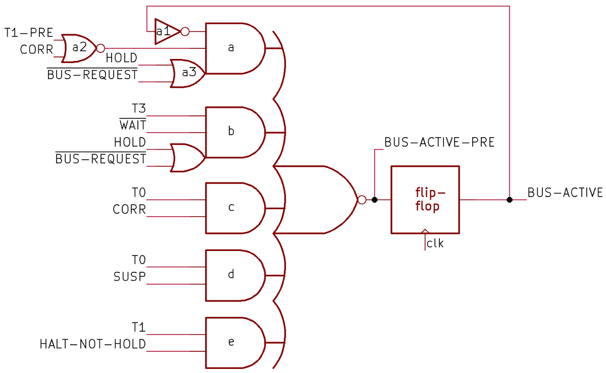
BUS-ACTIVE is generated by the complex circuit below that determines if the bus will be active,
specifically in states T0 through T3.
Because of the flip-flop, the computation of BUS-ACTIVE happens in the previous clock cycle.
In more detail, the signal BUS-ACTIVE-PRE indicates if the bus cycle will continue or will end on the next clock cycle.
Delaying this signal through the flip-flop generates BUS-ACTIVE, which indicates if the bus is currently active in states T0 through T3.
The top AND gate (a) is responsible for starting a cycle or keeping a cycle going (a1).
It will allow a new cycle if there is a bus request (without HOLD) (a3).
It will also allow a new cycle if there is a CORR micro-instruction prior to the T1 state (even if there is a HOLD, since
this "fake" cycle won't use the bus) (a2).
Finally, it allows a new cycle for a HALT, using T1-pre (a2).10
Next are the special cases that end a bus cycle.
The second AND gate (b) ends the bus cycle after T3 unless there is a wait state or another bus request.
(But a HOLD will block the next bus request.)
The remaining gates end the cycle after T0 to preempt a prefetch if a CORR or SUSP micro-instruction occurs (d), or
end after T1 for a HALT (e).
The BUS-ACTIVE circuit above uses a complex gate, a 5-input NOR gate fed by 5 AND gates with two attached OR gates. Surprisingly,
this is implemented in the processor as a single gate with 14 inputs.
Due to how gates are implemented with NMOS transistors, it is straightforward to implement this as a single gate.
The inverter and NOR gate on the left, however, needed to be implemented separately, as they involve inversion;
an NMOS gate must have a single inversion.
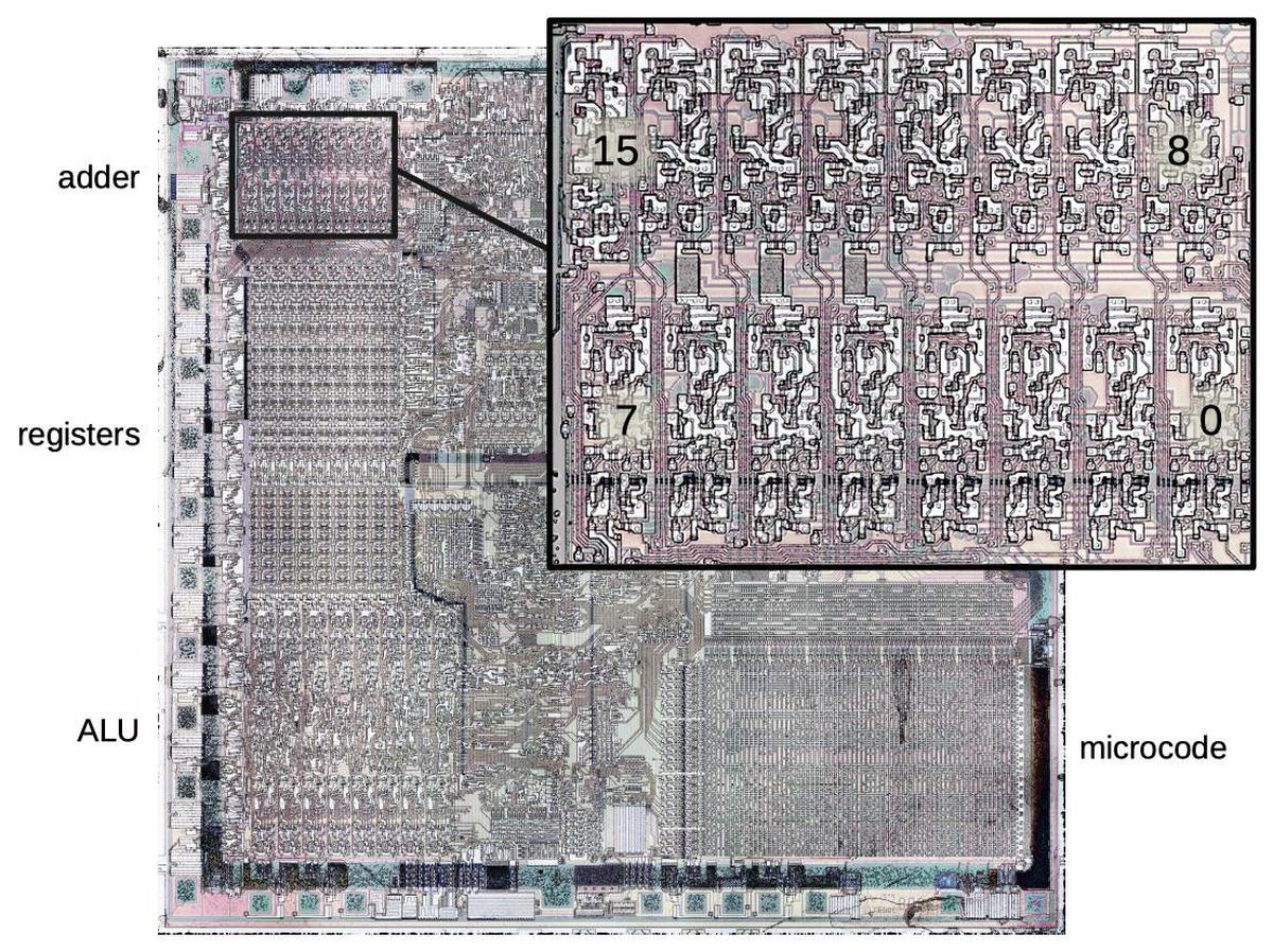
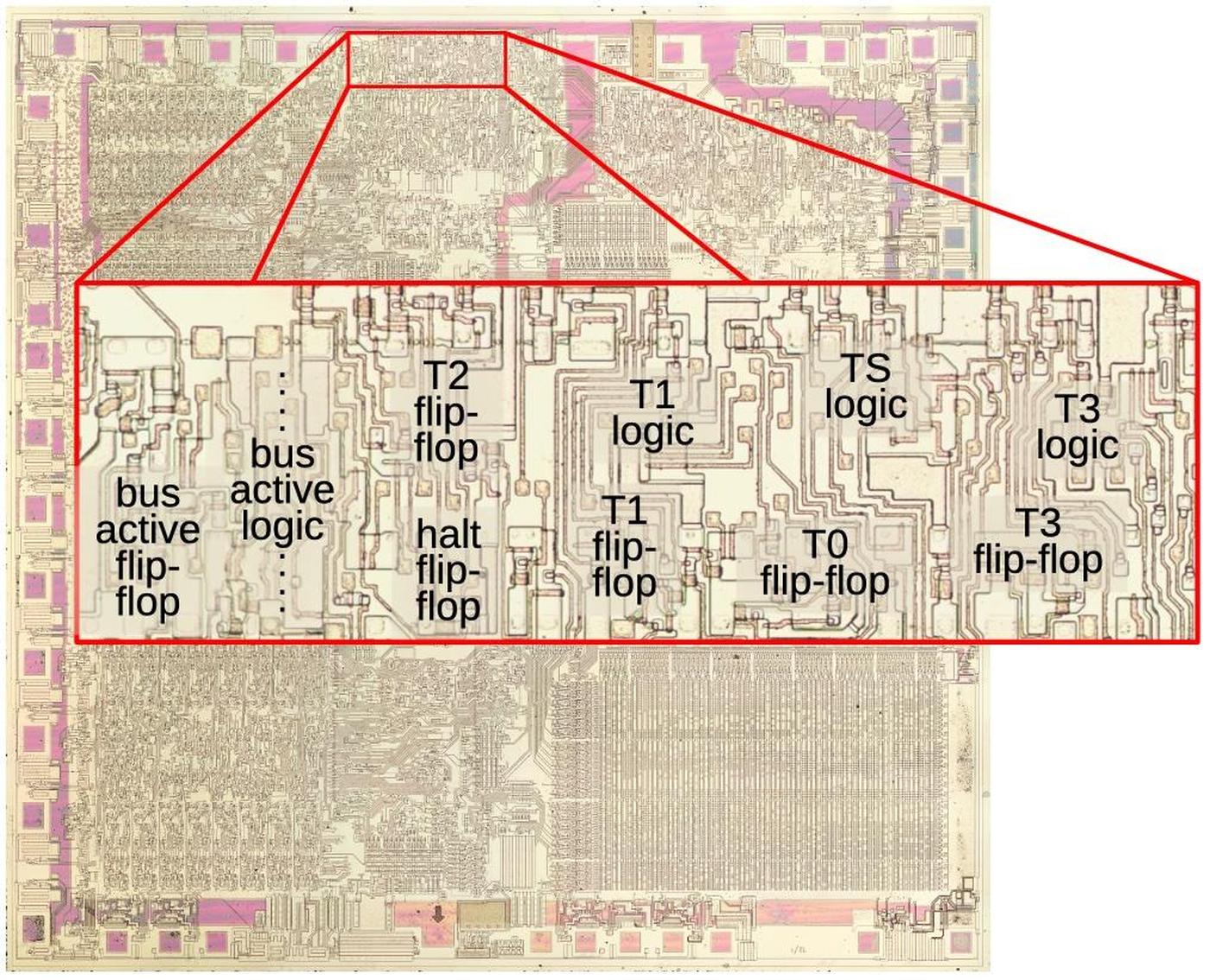
The diagram above shows the layout of the bus state machine circuitry on the die, zooming in on the top region of the die. The metal layer has been removed to expose the underlying silicon and polysilicon. The layout of each flip-flop is completely different, since the layout of each transistor is optimized to its surroundings. (This is in contrast to later processors such as the 386, which used standard-cell layout.) Even though the state machine consists of just a handful of flip-flops and gates, it takes a noticeable area on the die due to the large 3.2 µm feature size of the 8088. (Modern processors have features measured in nanometers, not micrometers.)
Conclusions
The bus state machine is an example of how the 8088's design consists of complications on top of complications.
While the four-state bus cycle seems straightforward at first, it gets more complicated due to prefetching,
wait states, the HALT instruction, and the bus hold feature, not to mention the interactions between these features.
While there were good motivations behind these features, they made the processor considerably more complicated.
Looking at the internals of the 8088 gives me a better understanding of why simple RISC processors became popular.
The bus state machine is a key part of the read and write circuitry, moving the bus operation through the necessary T-states. However, the state machine is not the only component in this process; a higher-level circuit decides when to perform a read, write, or prefetch, as well as breaking a 16-bit operation into two 8-bit operations.11 These circuits work together with the higher-level circuit telling the state machine when to go through the states.
In my next blog post, I'll describe the higher-level memory circuit so follow me on Twitter @kenshirriff or RSS for updates. I'm also on Mastodon as oldbytes.space@kenshirriff. If you're interested in the 8086, I wrote about the 8086 die, its die shrink process, and the 8086 registers earlier.
Notes and references
-
The 8085 and 8088 processors both use a 4-step bus cycle for instruction fetching. For other reads and writes, the 8085's bus cycle has three steps compared to four for the 8088. Thus, the 8085 and 8088 bus cycles are similar but not an exact match. ↩
-
The 8088 has separate instructions to read or write an I/O device. From the bus perspective, there's no difference between an I/O operation and a memory operation except that a pin on the chip indicates if the operation is for memory or I/O.
The 8088 supports I/O operations for historical reasons, going back through the 8086, 8080, 8008, and the Datapoint 2200 system. In contrast, many other contemporary processors such as the 6502 used memory-mapped I/O, using standard memory accesses for I/O devices.
The 8086 has a pin M/IO that is high for a memory access and low for an I/O access. External hardware uses this pin to determine how to handle the request. Confusingly, the pin's function is inverted on the 8088, providing IO/M. One motivation behind the 8088's 8-bit bus was to allow reuse of peripherals from the earlier 8-bit 8085 processor. Thus, the pin's function was inverted so it matched the 8085. (The pin is only available when the 8086/8088 is used in "minimum mode"; "maximum mode" remaps some of the pins, making the system more complicated but providing more control.) ↩
-
I've made the timing diagram somewhat idealized so actions line up with the clock. In the real datasheet, all the signals are skewed by various amounts so the timing is more complicated. See the datasheet for pages of timing constraints on exactly when signals can change. ↩
-
For more information on the implementation of the address adder, see my previous blog post. ↩
-
The
POPoperation is an example of how the address adder updates a memory pointer. In this case, the stack address is moved from the Stack Pointer to theINDregister in order to perform the memory read. As part of the read operation, theINDregister is incremented by 2. The address is then moved from theINDregister to the Stack Pointer. Thus, the address adder not only performs the segment arithmetic, but also computes the new value for theSPregister.Note that the increment/decrement of the
INDregister happens after the memory operation. For stack operations, the SP must be decremented before aPUSHand incremented after aPOP. The adder cannot perform a predecrement, so thePUSHinstruction uses the ALU (Arithmetic/Logic Unit) to perform the decrement. ↩ -
During the
CORRmicro-instruction, the Bus Interface Unit performs specialTSandT0states. Note that these states don't have any external effect, so they are invisible outside the processor. ↩ -
The tradeoff with memory boards was that slower RAM chips were cheaper. The better RAM boards advertised "no wait states", but cheaper boards would add one or more wait states to every access, reducing performance. ↩
-
Only the second half of the
TSstate has an effect on the Bus Interface Unit, soTSis not a full state like the other states. Specifically, a delayedTSsignal is taken from the first half of theT0flip-flop, and this signal is used to control various actions in the Bus Interface Unit. (Alternatively, you could think of this as an earlyT0state.) This is why there isn't a separate flip-flop for theTSstate. I suspect this is due to timing issues; by the time theTSstate is generated by the logic, there isn't enough time to do anything with the state in that half clock cycle, due to propagation delays. ↩ -
There is a bit more circuitry for the
T1state for aHALT. Specifically, there is a flip-flop that is set on this signal. On the next cycle, this flip-flop both blocks the generation of anotherT1state and blocks the previousT1state from progressing toT2. In other words, this flip-flop makes sure the specialT1lasts for one cycle. However, aHOLDstate resets this flip-flop. That allows another specialT1to be generated when theHOLDends. ↩ -
The trickiest part of this circuit is using
T1-preto start a (short) cycle forHALT. The way it works is that theT1-presignal only makes a difference if there isn't a bus cycle already active. The only way to get an "unexpected"T1-presignal is if the state machine generates it for the first cycle of aHALT. Thus, theHALTtriggersT1-preand thus thebus-activesignal. You might wonder why thebus-activeuses this roundabout technique rather than getting triggered directly byHALT. The motivation is that the specialT1state forHALTrequires the AND of three signals to ensure that the state is generated once for theHALTrather than continuously, but happens again after aHOLD, and waits until the current bus cycle is done. Instead of duplicating that AND gate, the circuit usesT1-prewhich incorporates that logic. (This took me a long time to figure out.) ↩ -
The 8088 has a 16-bit bus, compared to the 8088's 8-bit bus. Thus, a 16-bit bus operation on the 8088 will always require two 8-bit operations, while the 8086 can usually perform this operation in a single step. However, a 16-bit bus operation on the 8086 will still need to be broken into two 8-bit operations if the address is unaligned (i.e. odd). ↩
