This post describes our continuing efforts to restore a Xerox Alto. We checked that the low-level microcode tasks are running correctly and the processor is functioning. (The Alto uses an unusual architecture that runs multiple tasks in microcode.) Unfortunately the system still doesn't boot from disk, so the next step will be to get out the logic analyzer and see exactly what's happening. Here's Marc's video of the days's session:
The Alto was a revolutionary computer, designed at Xerox PARC to investigate personal computing, introducing the GUI, Ethernet and laser printers to the world. Y Combinator received an Alto from computer visionary Alan Kay. I'm helping restore the system, along with Marc Verdiell, Luca Severini, Ron Crane, Carl Claunch and Ed Thelen (from the IBM 1401 restoration team). For background, see my previous restoration articles: day 1, day 2, day 3.
Checking the clocks
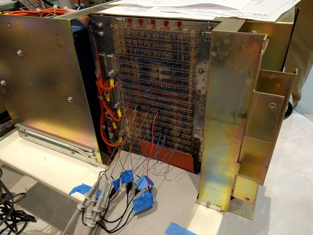
We started by checked that all the clock signals were working properly by connecting an oscilloscope to the wirewrap pins on the computer's backplane. This took a lot of careful counting to make sure we connected to the right pins! The system clock signals are generated by an oscillator on the video display card, which isn't where I'd expect to find them. Since the clock signals control the timing of the entire system, nothing will happen if the clock is bad. Thus, checking the clock was an important first step.At first, the clock signals all looked awful, but after finding a decent ground for the oscilloscope probes, the clock signals looked much better. We verified that the multiple clock outputs were all running nicely. We also tested the reset line to make sure it was being triggered properly - the Alto is reset by pushing a button at the back of the keyboard.
Microcode tasks
Next we looked at the running tasks. The Alto has 16 separate tasks running in microcode, doing everything from pushing pixels to the display to refreshing memory to moving disk words. Keep in mind that these are microcode tasks, not operating-system level tasks. The Alto was designed to reduce hardware by performing as many tasks in software as possible to reduce price and increase flexibility. The downside is the CPU can spend the majority of its time doing these tasks rather than "useful" work.Alto task scheduling is fairly complex. Each task has a priority. When a task is ready to run, its request line is activated (by the associated hardware). The current task can offer to yield by executing the TASK function at convenient points. If there is a higher-priority task ready to run, it preempts the running task. If there's nothing better to run, task 0 runs - this task is what actually runs user code, emulating the Data General Nova instruction set.
The point of this explanation is that microcode instructions need to be running properly for task switching to happen. If the TASK function doesn't get called, the current task will run forever. And if all the task scheduling hardware isn't working right, task switching also won't happen.
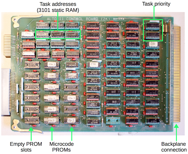
Below is a picture of the microcode control board from the Alto. When you're using 1973-era chips, it takes a lot of chips to do anything. This board manages which task is running and the memory address of each task. It uses two special priority encoder chips to determine which waiting task has the highest priority. The board holds the microcode, 1024 micro-instructions of 32 bits each, using eight 1K x 4 bit PROM chips. (PROM, programmable read-only memory, is sort of like non-erasable flash memory.) The board has 8 open sockets allowing an upgrade of 1K of additional microcode to be installed. Note the tiny memory capacity of the time, just 512 bytes of storage per chip.
Since tasks can be interrupted, the board needs to store the current address of each task. It uses two i3101A RAM chips for this storage. The 3101 is historically interesting: it was the first solid state memory chip, introduced by Intel in 1969. This chip holds 64 bits as 16 words of 4 bits each. Just imagine a time when a memory chip held not gigabits but just 64 total bits.
Looking at the running tasks
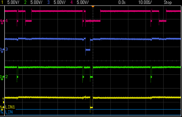
The control board has a 4-bit task number available on the backplane, indicating which task is running. We hooked up the oscilloscope so we could see the running tasks. The good news is we saw the appropriate tasks running at the right intervals, with preemption working properly. The following traces show the four task number bits. Most of the time the low-priority task 0 runs (all active-low signals high). Task 12 is running in the middle. Task 8 (memory refresh) runs three times, 38.08 microseconds apart as expected. From the traces, everything seems to be functioning correctly with the task execution.
Seeing the running tasks is a big thing, since it shows a whole lot of the system is working properly. As explained earlier, since tasks are running and switching, the microcode processor must be fetching and executing micro-instructions correctly.
Display working better now
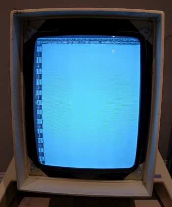
You may remember from the previous article that the Alto display was very, very dim and we suspected the CRT was failing. The good news is the display has steadily increased in brightness from its original very dim state, so we probably won't need to replace the CRT. We also managed to see some garbage on the screen along with a cursor, showing that RAM is storing something and the display interface is working.
Boot still doesn't work
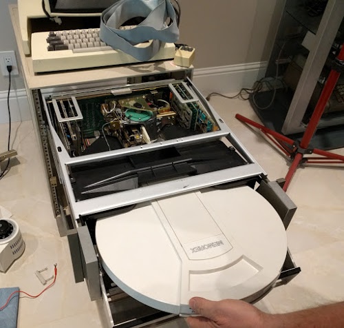
Lots of things are working at this point. The minor :-) remaining problem is the system doesn't boot. Last time, we got the disk drive working: we can put a 14-inch disk cartridge (below) in the drive, the drive spins up, and the heads load. But looking at the backplane signals, we found nothing is getting read from the disk (which explains the boot failure). The oscilloscope showed that the Alto isn't sending any commands to the disk - the Alto isn't even trying to read the disk. We checked for various hardware issues and couldn't find any problems. My suspicion is the boot code in microcode isn't running properly.
A bit of explanation on the boot process: On reset, microcode task 0 handles the boot. If backspace is pressed on the keyboard, the Alto does a Ethernet boot. Otherwise it does a disk boot by setting up a disk command block in RAM. The microcode disk sector task gets triggered on each sector pulse (which we saw coming from the disk). It checks if there is a command block in RAM, and if so sends the command to the disk. When the read data comes from the disk, the disk word task copies the data into memory. At the end, the block read from disk will be executed, performing the disk boot. So three microcode tasks need to cooperate to boot from disk.
Since we're seeing no command sent to the disk, something must be going wrong between task 0 setting up the command block in RAM and the sector task executing the command block. There's a lot that needs to go right here. If anything is wrong in the ALU or RAM has problems, the command block will get corrupted. And then no disk operation will happen.
Conclusion
The next step is to use a logic analyzer to see exactly what is running, instruction by instruction. By looking at the microcode address lines, we will be able to see what code is executing and where things go wrong. Then we can probe the memory bus to see if RAM is the problem, and look at the ALU to see if it is causing the problem. This is where debugging will get more complex.I've studied the microcode and it is very bizarre. (You can see the source here.) Instructions are in random order in the PROM, what an instruction does depends on what task is running, branches happen when a device board flips address bits on the bus, and some bits in the PROM are inverted for no good reason (probably to save an inverter chip somewhere). So looking at the microcode can be mind-bending. But hopefully with the logic analyzer we can narrow the problem down. We can also use the Living Computer Museum's simulator to cross-check against what microcode should be running.
For updates on the restoration, follow kenshirriff on Twitter.
5 comments:
Hi Ken,
Several things come to mind here:
1. I see socketed chips here and weep. I think of everytime I see a socketed chip and the issues that it caused. I also think of how the chassis was sitting in some corner of some warehouse collecting dust and being exposed to changes of temperature and humidity. I'm thinking of dissimilar metals making contact. And I'm thinking of thousands of connections...
2. Wire Wrapped Backplane. I'm wondering about the insulation of the 30 gauge wire. Sitting in that warehouse for years. I'd look for discoloration of the metal where it comes in contact with the posts. The NASA spec on wire wrapping called for 'modified gas tight' wraps. Truth of the matter was the tension of the wrap caused the wire to bite into the corners of the posts for the connection. Over the years, you wonder how well something like that holds up. The wire BTW, contains two levels of insulation. The base being the colored layer. The outer layer being clear. Im wondering if the insulation properties have deteriorated and become brittle. The problem here will be at places where the wire routes around a third party post and can rub against the post. Looking at your Oscope photo, I saw the 'overshoot' and ringing that was so characteristic of signals on a wire wrapped backplane. Some things you don't forget. ;D
3. On bootup: Do you have the means to manually step through the micro code. Also, you can monitor just how it progresses through the micro code listing step by step. Yes, it's tedious but you gain great insight in just how clever the code actually was. If the design was based on an ALU chip you see that the instructions could be 'pipelined'. That is, several instructions are being executed at once. Knowing that fact - explains why the next two instructions may have been executed before before the 'branch' took place in a listing.
After working on a project like this, you really can appreciate how interesting it was to develop micro code around the architecture of the chips.
Best,
@riverkey2640
I think socketed chips are sort of a tradeoff, especially on early gear. The chips themselves were expensive and likely had a higher failure rate than comparable modern parts, so you didn't want to be constantly desoldering and resoldering chips (or unwinding and rewinding wirewrap connections) and running the risk of wrecking something else.
I remember that satisfying "crunch" of re-seating chips that worked their way a little bit out of each IC socket. Better than a roll of bubble wrap.
It's unfortunate that the microcode space is so small that there wasn't enough room to put in some basic diagnostic code. The PERQ (designed five or six years later) had 4k of microcode store, which meant the boot microcode could start with some tests of the CPU to ensure that microcode jumps, ALU operations and CPU registers were all working before it started trying to boot anything (there was a handy 2x7-segment LED display on the underside (!) of the keyboard which told you how far through the boot process the microcode had got).
The PERQ had the same "will put instructions anywhere in the PROM because microcode jumps are free" trick, which the microcode assembler automatically did for you to fit everything in.
Having debugged a broken Alto some 40 years ago, I can relate. I put the (dreaded) logic analyzer (a Biomation K-100D for those who care) on the microcode address bits. I watched the address until the machine hung. I used the microcode listing to figure out why it was hanging, replaced the appropriate gate and just like that it was working again. This was assisted by the backplane that had nice wirewrap pins where I could push on the logic analyzer probes.
Post a Comment