Restoring Y Combinator's Xerox Alto, day 4: What's running on the system

This post describes our continuing efforts to restore a Xerox Alto. We checked that the low-level microcode tasks are running correctly and the processor is functioning. (The Alto uses an unusual architecture that runs multiple tasks in microcode.) Unfortunately the system still doesn't boot from disk, so the next step will be to get out the logic analyzer and see exactly what's happening. Here's Marc's video of the days's session:

The Alto was a revolutionary computer, designed at Xerox PARC to investigate personal computing, introducing the GUI, Ethernet and laser printers to the world. Y Combinator received an Alto from computer visionary Alan Kay. I'm helping restore the system, along with Marc Verdiell, Luca Severini, Ron Crane, Carl Claunch and Ed Thelen (from the IBM 1401 restoration team). For background, see my previous restoration articles: day 1, day 2, day 3.

Checking the clocks

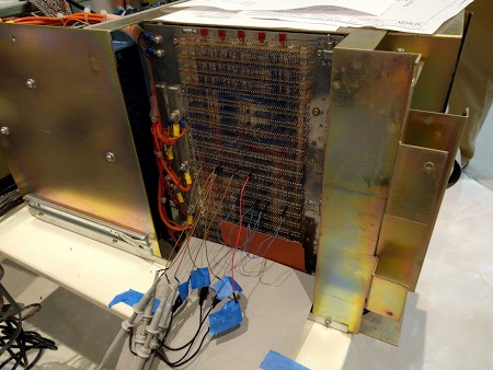
We started by checked that all the clock signals were working properly by connecting an oscilloscope to the wirewrap pins on the computer's backplane. This took a lot of careful counting to make sure we connected to the right pins! The system clock signals are generated by an oscillator on the video display card, which isn't where I'd expect to find them. Since the clock signals control the timing of the entire system, nothing will happen if the clock is bad. Thus, checking the clock was an important first step.

At first, the clock signals all looked awful, but after finding a decent ground for the oscilloscope probes, the clock signals looked much better. We verified that the multiple clock outputs were all running nicely. We also tested the reset line to make sure it was being triggered properly - the Alto is reset by pushing a button at the back of the keyboard.

Connecting an oscilloscope to the Xerox Alto backplane

Connecting oscilloscope probes to the Xerox Alto backplane.

Microcode tasks

Next we looked at the running tasks. The Alto has 16 separate tasks running in microcode, doing everything from pushing pixels to the display to refreshing memory to moving disk words. Keep in mind that these are microcode tasks, not operating-system level tasks. The Alto was designed to reduce hardware by performing as many tasks in software as possible to reduce price and increase flexibility. The downside is the CPU can spend the majority of its time doing these tasks rather than "useful" work.

Alto task scheduling is fairly complex. Each task has a priority. When a task is ready to run, its request line is activated (by the associated hardware). The current task can offer to yield by executing the TASK function at convenient points. If there is a higher-priority task ready to run, it preempts the running task. If there's nothing better to run, task 0 runs - this task is what actually runs user code, emulating the Data General Nova instruction set.

The point of this explanation is that microcode instructions need to be running properly for task switching to happen. If the TASK function doesn't get called, the current task will run forever. And if all the task scheduling hardware isn't working right, task switching also won't happen.

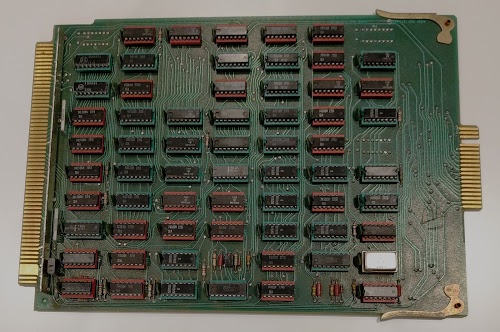
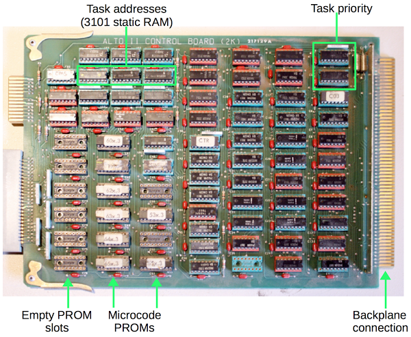
Below is a picture of the microcode control board from the Alto. When you're using 1973-era chips, it takes a lot of chips to do anything. This board manages which task is running and the memory address of each task. It uses two special priority encoder chips to determine which waiting task has the highest priority. The board holds the microcode, 1024 micro-instructions of 32 bits each, using eight 1K x 4 bit PROM chips. (PROM, programmable read-only memory, is sort of like non-erasable flash memory.) The board has 8 open sockets allowing an upgrade of 1K of additional microcode to be installed. Note the tiny memory capacity of the time, just 512 bytes of storage per chip.

The microcode control board from a Xerox Alto

The microcode control board from a Xerox Alto

Since tasks can be interrupted, the board needs to store the current address of each task. It uses two i3101A RAM chips for this storage. The 3101 is historically interesting: it was the first solid state memory chip, introduced by Intel in 1969. This chip holds 64 bits as 16 words of 4 bits each. Just imagine a time when a memory chip held not gigabits but just 64 total bits.

Looking at the running tasks

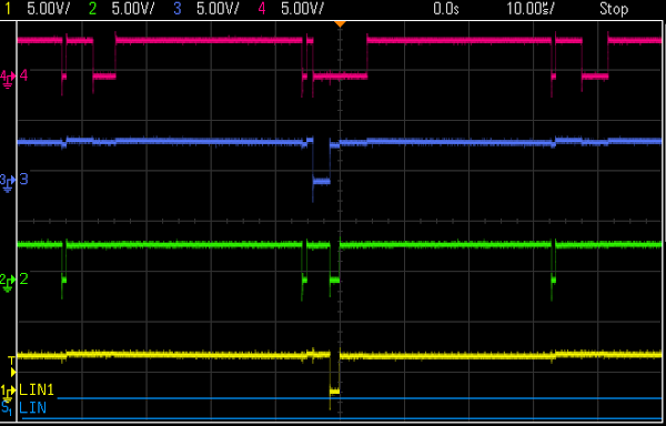
The control board has a 4-bit task number available on the backplane, indicating which task is running. We hooked up the oscilloscope so we could see the running tasks. The good news is we saw the appropriate tasks running at the right intervals, with preemption working properly. The following traces show the four task number bits. Most of the time the low-priority task 0 runs (all active-low signals high). Task 12 is running in the middle. Task 8 (memory refresh) runs three times, 38.08 microseconds apart as expected. From the traces, everything seems to be functioning correctly with the task execution.

The 4-bit microcode task select lines on the Xerox Alto

Trace of the 4-bit microcode task select lines on the Xerox Alto. Top (red) is 8, then 4, 2 and bottom (yellow) is 1 bit. Signals are active-low. Each time interval is 10 microseconds, so this shows a 100 microsecond time interval.

Seeing the running tasks is a big thing, since it shows a whole lot of the system is working properly. As explained earlier, since tasks are running and switching, the microcode processor must be fetching and executing micro-instructions correctly.

Display working better now

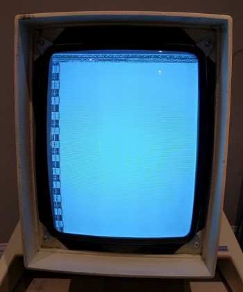
You may remember from the previous article that the Alto display was very, very dim and we suspected the CRT was failing. The good news is the display has steadily increased in brightness from its original very dim state, so we probably won't need to replace the CRT. We also managed to see some garbage on the screen along with a cursor, showing that RAM is storing something and the display interface is working.

The display of the Xerox Alto displaying random junk.

The display of the Xerox Alto displaying random junk.

Boot still doesn't work

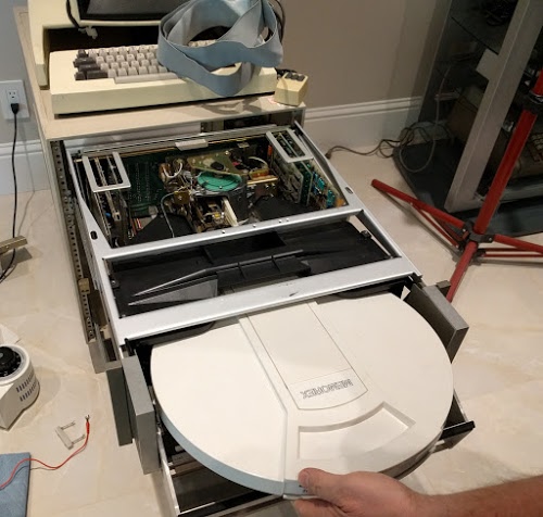
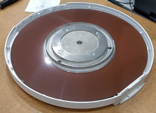
Lots of things are working at this point. The minor :-) remaining problem is the system doesn't boot. Last time, we got the disk drive working: we can put a 14-inch disk cartridge (below) in the drive, the drive spins up, and the heads load. But looking at the backplane signals, we found nothing is getting read from the disk (which explains the boot failure). The oscilloscope showed that the Alto isn't sending any commands to the disk - the Alto isn't even trying to read the disk. We checked for various hardware issues and couldn't find any problems. My suspicion is the boot code in microcode isn't running properly.

Inserting a hard disk into the Diablo drive.

Inserting a hard disk into the Diablo drive.

A bit of explanation on the boot process: On reset, microcode task 0 handles the boot. If backspace is pressed on the keyboard, the Alto does a Ethernet boot. Otherwise it does a disk boot by setting up a disk command block in RAM. The microcode disk sector task gets triggered on each sector pulse (which we saw coming from the disk). It checks if there is a command block in RAM, and if so sends the command to the disk. When the read data comes from the disk, the disk word task copies the data into memory. At the end, the block read from disk will be executed, performing the disk boot. So three microcode tasks need to cooperate to boot from disk.

Since we're seeing no command sent to the disk, something must be going wrong between task 0 setting up the command block in RAM and the sector task executing the command block. There's a lot that needs to go right here. If anything is wrong in the ALU or RAM has problems, the command block will get corrupted. And then no disk operation will happen.

Conclusion

The next step is to use a logic analyzer to see exactly what is running, instruction by instruction. By looking at the microcode address lines, we will be able to see what code is executing and where things go wrong. Then we can probe the memory bus to see if RAM is the problem, and look at the ALU to see if it is causing the problem. This is where debugging will get more complex.

I've studied the microcode and it is very bizarre. (You can see the source here.) Instructions are in random order in the PROM, what an instruction does depends on what task is running, branches happen when a device board flips address bits on the bus, and some bits in the PROM are inverted for no good reason (probably to save an inverter chip somewhere). So looking at the microcode can be mind-bending. But hopefully with the logic analyzer we can narrow the problem down. We can also use the Living Computer Museum's simulator to cross-check against what microcode should be running.

For updates on the restoration, follow kenshirriff on Twitter.
Restoring Y Combinator's Xerox Alto, day 3: Inside the disk drive

I'm helping restore a Xerox Alto — a legendary minicomputer from 1973 that helped set the direction for personal computing. This post describes how we cleaned and restored the disk drive and then powered up the system. Spoiler: the drive runs but the system doesn't boot yet.

While creating the Alto, Xerox PARC invented much of the modern personal computer: everything from Ethernet and the laser printer to WYSIWYG editors with high-quality fonts. Getting this revolutionary system running again is a big effort but fortunately I'm working with a strong team: Marc Verdiell, Luca Severini, Ron Crane, Carl Claunch and Ed Thelen, along with special guest Tim Curley from PARC.

If this article gives you deja vu, you probably saw Marc's restoration video (above) on Hacker News last week or read the earlier restoration updates: introduction, day 1, day 2.

Hard disk technology of the 1970s

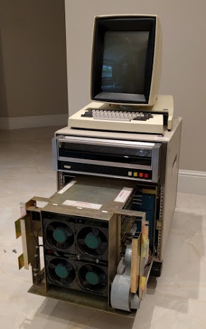
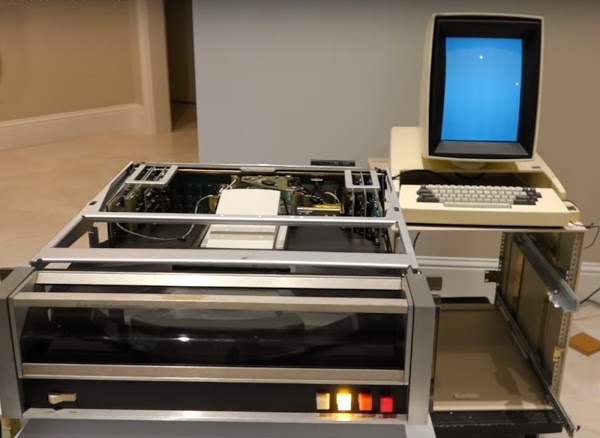
For mass storage, the Alto uses a Diablo disk drive, which stores 2.5 megabytes on a removable 14 inch disk cartridge. With 1970s technology, you don't get much storage even on an inconveniently large disk, so Alto users were constantly short of disk space. The photo below shows the Xerox Alto, with the computer chassis (bottom) partially removed. Above the chassis and below the keyboard is the Diablo disk drive, which is the focus of this article.

The Xerox Alto II XM 'personal computer'. The card cage below the disk drive has been partially removed. Four cooling fans are visible at the front of it.

The Xerox Alto II XM 'personal computer'. The card cage below the disk drive has been partially removed. Four cooling fans are visible at the front of it.

To insert the disk cartridge into the drive, the front of the drive swings down and the cartridge slides into place. The cartridge is an IBM 2315 disk pack, which was used by many manufacturers of the era such as DEC and HP, and contains a single platter inside the hard white protective case. The disk drive has been partially pulled out of the cabinet and the top removed, revealing the internals of the drive. During normal use, the disk drive is inside the cabinet, of course.

Inserting a hard disk into the Diablo drive.

Inserting a hard disk into the Diablo drive.

Unlike modern hard disks, the Alto's disk is not sealed; the disk pack opens during use to provide access to the heads. To protect against contamination and provide cooling, filtered air is blown through the disk pack during use. Air enters the disk through a metal panel on the bottom of the disk (as seen below) and exits through the head opening, blowing any dust away from the disk surface.

Hard disk for the Xerox Alto, showing the air intake vent.

Hard disk for the Xerox Alto, showing the air intake vent.

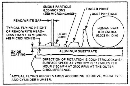
Although the heads are widely separated during disk pack insertion, they move very close to the disk surface during operation, floating on a cushion of air about one thousandth of a millimeter above the surface. The diagram below from the manual illustrates the danger of particles on the disk's surface. Any contamination can cause the head to crash into the disk surface, gouging out the oxide layer and destroying the disk and the head.

The Diablo disk and why contaminants are bad, from the Alto disk manual.

The Diablo disk and why contaminants are bad, from the Alto disk manual.

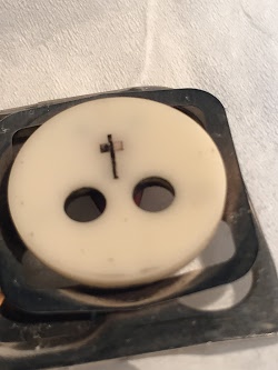
The magnified photo below shows the read/write head. The two air bleed holes ensure that the head is flying at the correct height above the disk surface. The long part of the cross contains the read/write coil, while the short part of the cross contains the erase coils (which erase a band between tracks).

Read/write head for the Diablo drive.

Read/write head for the Diablo drive.

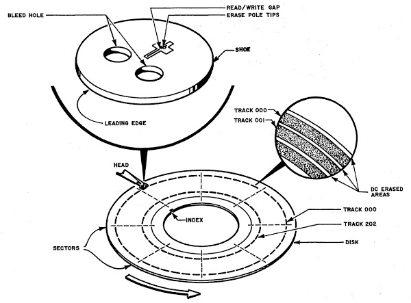
The following diagram shows how data is stored on the disk in 203 tracks (actually 203 cylinders, since there are tracks on the top and bottom surfaces). The drive moves the tiny read/write heads to the desired track. Each track is divided into 12 sectors, with 256 words of data in each sector.

Diagram of how the Diablo disk drive's read/write head stores data in tracks on the disk surface. From the Maintenance Manual.

Diagram of how the Diablo disk drive's read/write head stores data in tracks on the disk surface. From the Maintenance Manual.

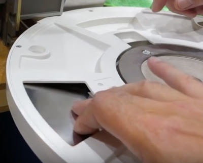
In the photo below, we have removed the top of the disk pack revealing the hard disk inside. Note the vertical metal ring along the inside of the disk; it has twelve narrow slots that physically indicate the twelve sectors of the disk. A double slot is the index mark, indicating the first sector. To make sure the disk surface was clean, we wiped the disk surfaces clean with isopropyl alcohol. This seemed a bit crazy to me, but apparently it's a normal thing to do with disks of that era.

Inside the disk pack used by the Xerox Alto.

Inside the disk pack used by the Xerox Alto.

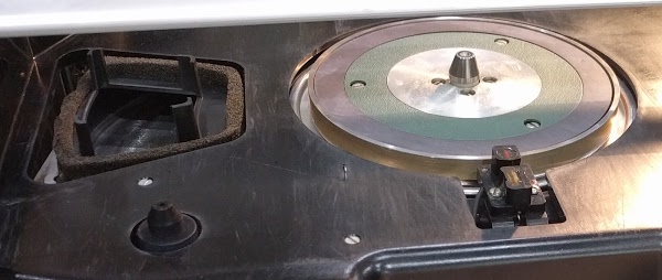
The photo below shows the motor spindle that rotates the hard disk at 1500 RPM. In front of the spindle, you can see the sensor that detects the slots that indicate sectors. To the left is the air duct that provides filtered airflow into the disk pack. (The air intake on the bottom of the disk pack was shown in an earlier photo.) Around the edge of the air duct is foam to provide a seal between the duct and the disk cartridge, ensuring airflow through the cartridge.

The motor spindle (center) rotates the hard disk. In front of the spindle is the sensor to detect sectors. To the left is the ventilation air duct for the disk.

The motor spindle (center) rotates the hard disk. In front of the spindle is the sensor to detect sectors. To the left is the ventilation air duct for the disk.

After 40 years, the foam had deteriorated into mush and needed to be replaced. The foam no longer provided an airtight seal. Even worse, particles could break off the foam. If a piece of foam got blown onto the disk surface, it would probably trigger a catastrophic disk crash. To replace the foam, we used weatherstripping, which isn't standard but seemed to get the job done.

As well as replacing the foam, we vacuumed any dust out of the drive and carefully cleaned the heads and other drive components.

How the Diablo drive works

The drive itself has fairly limited logic, with most of the functionality inside the Alto. The drive can seek to a particular track, indicate the current sector, and read or write a stream of raw bits. Since there's no buffering in the disk drive, the Alto must supply every bit at the precise time based on the disk's rotation. In the Alto, microcode performs many interfacing tasks that are usually done in hardware. Instead of using DMA, the Alto's microcode moves data words one at a time to the disk interface card in the Alto, which does the serial/parallel conversion.

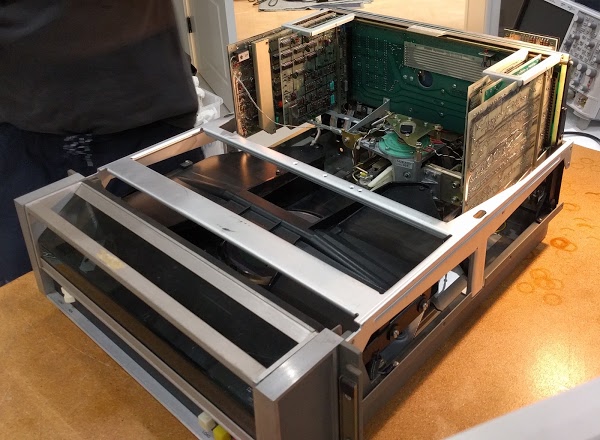
The Diablo drive opened for servicing.

The Diablo drive opened for servicing.

Modern disk drives use a dense disk controller integrated circuit. The Diablo drive, in contrast, implements its limited functionality with transistors and individual chips (mostly gates and flip flops), so it requires boards of components. The photo above shows the 6 main circuit boards of the Alto, plugged into the "mother board": three on the left side and three on the right side. For ease of maintenance, the electronics assembly pops up as seen above, allowing access to the boards. The leftmost board is the analog circuitry, generating the write signals for the heads and amplifying the signals read back from the disk. You can see a wire running from the board to the read/write heads. The next board detects sector and index marks and controls the motor speed. The third board has a counter to keep track of the current sector number.

The three boards on the right perform seeks, moving the disk head to the desired track. The first board computes the difference between the previous track number and the requested track number. The next board counts tracks as the head moves to determine the distance remaining. The rightmost board controls the servo that moves the head to the right track. The seek servo has a four-speed drive, so the head moves rapidly at first and slows down as it approaches the right track, more sophistication than I expected. The Diablo drive manual has detailed schematics.

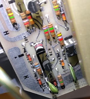
The photo below shows some of the colorful resistors and diodes on the analog read/write board, along with some transistors. Modern circuit boards would be much denser, with tightly packed surface mounted components.

Circuitry inside the Diablo 31 drive.

Circuitry inside the Diablo 31 drive.

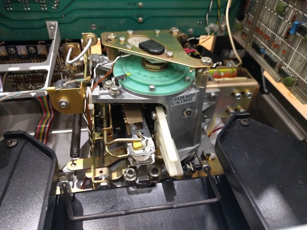
The head positioning mechanism is shown below. The turquoise circles rotate as the drive moves to a new track and the yellow pointer indicates the track number on the dial. The heads themselves are on the arm below (lower center). In front of the heads (bottom of the picture) is the metal bar that opens the disk pack when it is inserted.

Inside the Diablo disk drive. The heads are visible in the center. In front of them is the metal bar that opens the disk pack.

Inside the Diablo disk drive. The heads are visible in the center. In front of them is the metal bar that opens the disk pack.

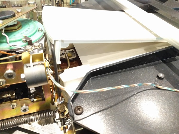
As the disk pack enters the drive, it opens up to provide access to the disk surface. The photo below shows the same mechanism as the previous photo, but from the side and with a disk inserted. You can see the exposed surface of the disk, brownish from the magnetizable iron oxide layer over the aluminum platter. As described earlier, the airflow exits the cartridge here, preventing dust from entering through this opening. The read/write head is visible above the disk's surface, with another head below the disk.

Closeup of the hard disk inside the Diablo drive. The read/write head (metal/yellow) is visible above the disk surface (brown).

Closeup of the hard disk inside the Diablo drive. The read/write head (metal/yellow) is visible above the disk surface (brown).

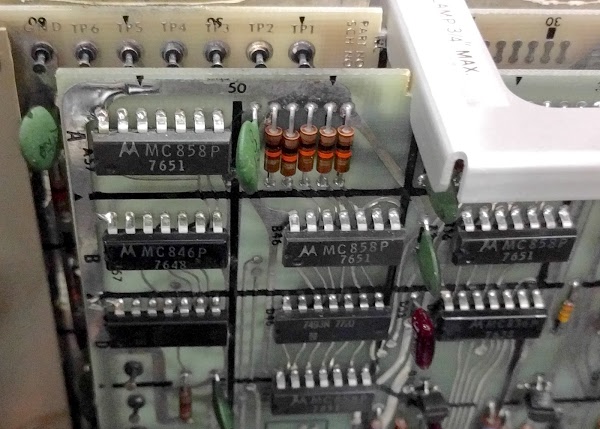
The drive largely uses primitive DTL chips—diode transistor logic, an early form of digital logic, as well as some slightly more modern TTL chips. The photo below shows some of the chips on the sector counting board. The chips labeled MC858P provide four NAND gates, so there's not much logic per chip. (7651 is the date code, indicating the chip was manufactured in week 51 of 1976.)

Chips on a control board for the Diablo drive.

Chips on a control board for the Diablo drive.

Conclusion

After putting the disk drive back together, we carefully powered up the system. The disk drive spun up to high speed, the heads dropped to the surface, and the disk slowed to 1500 RPM as expected. (One surprising complexity of the drive is it runs at a faster speed for a while so the airflow will blow contaminants out of the disk pack before loading the heads; it has counters and logic to implement this.) We verified that the disk surface remained undamaged, so the drive works properly, at least mechanically.

This was the first time we had powered up the Alto circuitry. Happily, nothing emitted smoke. But not surprisingly, the Alto failed to boot from the disk. Unless the Alto can read boot code from the disk (or Ethernet), nothing happens, not even a prompt on the screen. The photo below shows the disk with the ready light illuminated, and the empty screen.

The Xerox Alto's drive powered up, along with monitor (showing a white screen).

The Xerox Alto's drive powered up, along with monitor (showing a white screen).

We have a long debugging task ahead of us, to trace through the Alto's logic circuits and find out what's going wrong. We're also building a disk emulator using a FPGA, so we will be able to run the Alto with an emulated disk, rather than depending on the Diablo drive to keep running. The restoration is likely to keep us busy for a while, so expect more updates. One item we are missing is the Alignment Cartridge (or C.E. Pack), a disk cartridge with specially-recorded tracks used to align the drive; let us know if you happen to have one lying around!

For updates on the restoration, follow kenshirriff on Twitter. Thanks to Al Kossow and Keith Hayes for assistance with restoration.
Restoring Y Combinator's Xerox Alto, day 2: Repairing the display

This post describes how we repaired the monitor from a Xerox Alto. The Alto was a revolutionary computer, designed in 1973 at Xerox PARC to investigate personal computing. Y Combinator received an Alto from computer visionary Alan Kay, and I'm helping restore this system, along with Marc Verdiell, Luca Severini, Ron Crane, Carl Claunch and Ed Thelen. You may have seen Marc's restoration video (below) on Hacker News; my article describes the monitor repairs in more detail. (See my first article on the restoration for more background.)

The Alto display

One of the innovative features of the Alto was its 606 by 808 pixel bitmapped display, which could display high-quality proportionally spaced fonts as well as graphics. This display led to breakthroughs in computer interaction, such as the first WYSIWYG text editor, which could print formatted text on a laser printer (which Xerox had recently invented). This editor, Bravo, was written for the Alto by Charles Simonyi, who later wrote Word at Microsoft. (I discussed the Bravo editor in more detail last week.)

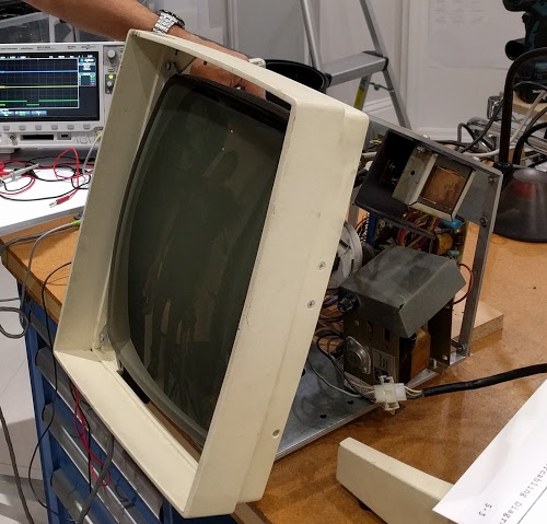
As you can see from the photos, the Alto's display has a somewhat unusual portrait orientation, allowing it to simulate an 8½x11 sheet of paper. Custom monitor hardware was required to support the portrait orientation, which uses 875 scan lines instead of the standard 525 lines. The Alto's monitor was based on a standard Ball Brothers computer monitor with some component values changed for the higher scan rate. This was easier than turning a standard monitor sideways and rotating everything in software.

The Xerox Alto's monitor with the case removed.

The Xerox Alto's monitor with the case removed.

How a CRT monitor works

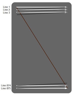
Since many readers may not be familiar with how CRTs work, I'll give a brief overview. The cathode ray tube (CRT) ruled television and computer displays from the 1930s until a decade or two ago, when flat panel displays finally won out. In a CRT, an electron beam is shot at a phosphor-coated screen, causing a spot on the screen to light up. The beam scans across the screen, left to right and top to bottom in a raster pattern. The beam is turned on and off, generating a pattern of dots on the screen to form the image.

The Xerox Alto's display uses a 875-line raster scan. (For simplicity, interlace is omitted from this diagram.)

The Xerox Alto's display uses a 875-line raster scan. (For simplicity, I'm ignoring interlacing of the raster scan.)

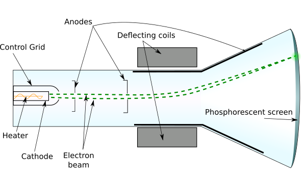
The cathode ray tube is a large vacuum tube containing multiple components, as shown below. A small electrical heater, similar to a light bulb filament, heats the cathode to about 1000°C. The cathode is an electrode that emits electrons when hot due to physics magic. The anode is positively charged with a high voltage (17,000V). Since electrons are negatively charged, they are attracted to the anode, causing a beam of electrodes to fly down the tube and slam into the screen. The screen is coated with a phosphor, causing it to glow where hit by the electron beam. A control grid surrounds the cathode; putting a negative voltage on the grid repels the electrons, reducing the beam strength and thus the brightness. Two electromagnets are arranged on the neck of the tube to deflect the beam horizontally and vertically; these are the deflection coils.

Diagram of a Cathode Ray Tube (CRT) . Based on drawings by Interiot and Theresa Knott  (CC BY-SA 3.0).

Diagram of a Cathode Ray Tube (CRT). Based on drawings by Interiot and Theresa Knott (CC BY-SA 3.0).

The components of the tube work together to control the image. The cathode voltage turns the beam on or off, allowing a spot to be displayed or not. The control grid controls the brightness of the display. The horizontal deflection coil scans the beam from left to right across the display, and then rapidly returns it to the left for the next line. The vertical deflection coil more slowly scans the beam from top to bottom, and then rapidly returns the beam to the top for the next image.

Monitors were built with the same CRT technology as televisions, but a television includes a tuner circuit to select the desired channel from the antenna. In addition, televisions have circuitry to extract the horizontal sync, vertical sync and video signals from the combined broadcast signal. These three signals are supplied to the Alto monitor separately, simplifying the circuitry. Color television is more complicated than the Alto's black and white display.

Getting the monitor operational

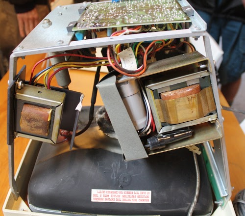
We started by removing the heavy metal case from the monitor, as seen below. The screen is at the bottom; the neck of the tube is hidden behind the components. The printed circuit board with most of the components is visible at the top. Unlike more modern displays that use integrated circuits, this display's circuitry is built from transistors. On the right is the power supply for the monitor, with a large transformer, capacitor, and fuse. On the left is the vertical drive transformer.

Inside the Alto's monitor. The screen is at the bottom. The power supply transformer is on the right and the vertical deflection transformer is on the left. The circuit board is at top.

Inside the Alto's monitor. The screen is at the bottom. The power supply transformer is on the right and the vertical deflection transformer is on the left. The circuit board is at top.

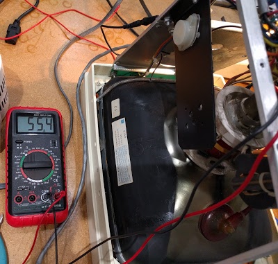
We started by checking out the 55 volt power supply that runs the monitor. This power supply is a linear power supply driven from the input AC. The input transformer produces about 68 volts, which is then dropped to 55 volts by a power transistor, controlled by a regulator circuit. (A few years later, more efficient switching power supplies were common in monitors.) It took some time to find the right place to measure the voltage, but eventually we determined that the power supply was working properly, as shown below. At the bottom of the photo below, you can also see the round, reddish connector that provides high voltage to the CRT tube; this is a separate circuit from the 55V power supply. (Grammar note: I consider CRT tube to be clearer, although technically redundant.)

Testing the 55V power supply in the Xerox Alto's monitor.

Testing the 55V power supply in the Xerox Alto's monitor.

At the top of the photo above, you can see the power transistor for the vertical deflection circuit. This circuit generates the vertical sweep signal, scanning from top to bottom 60 times a second. This signal is a sawtooth wave fed into the vertical deflection coil, so the beam is slowly deflected from top to bottom and then rapidly returns to the top. The vertical deflection signal is synchronized to the video input by a vertical sync input from the Alto.

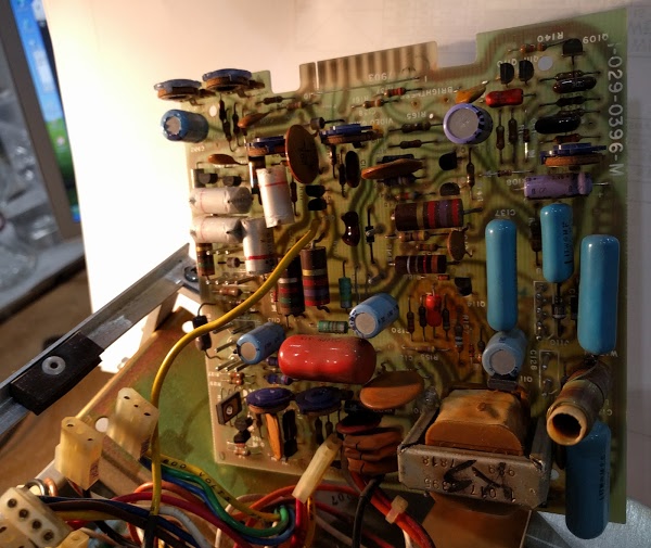
The monitor circuit board (below) contains circuitry for vertical deflection, horizontal deflection, 55V power supply regulation, and video amplification. The board isn't designed for easy repair; to access the components, many connectors (lower left) must be disconnected.

The circuit board for the Xerox Alto's monitor.

The circuit board for the Xerox Alto's monitor.

The horizontal deflection circuit generates the horizontal sweep signal, scanning from left to right about 26,000 times a second. Driving the deflection coils requires a current of about 2 amps, so this circuit must switch a lot of current very rapidly. I've heard that the horizontal circuitry on the Alto has a tendency to overheat. We noticed some darkened spots on the board, but it still works.

The horizontal deflection circuit also supplies 17,000 volts to the CRT tube. This voltage is generated by the flyback transformer. Each horizontal scanline sends a current pulse into the flyback transformer, which is a step-up transformer that produces 17,000 volts on its output. (Interestingly, phone chargers also use flyback transformers, but one that produces 5 volts rather than 17,000 volts.)

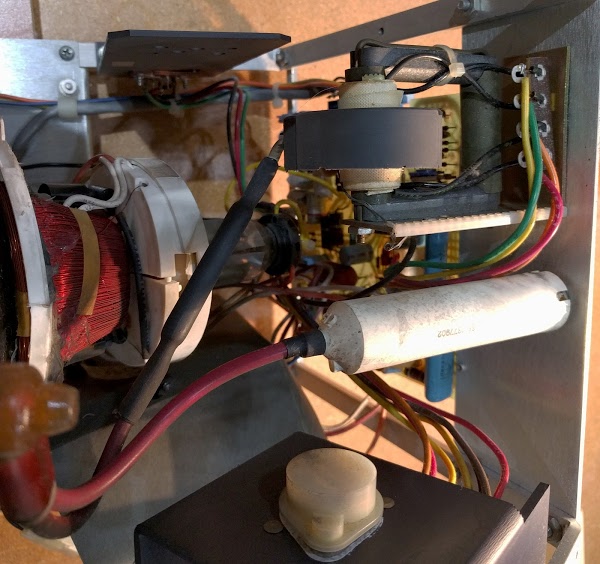
The photo below shows the flyback transformer (upper right), the UFO-like structure with a thick high-voltage wire leading to the CRT. The large white cylinder is the bleeder resistor that drains the high voltage away when the monitor is not in use. This unusually large resistor is 500 megaohms and 6 watts, and is connected to the tube by a thick, red high voltage wire. The deflection coils are visible at the left, coils of red wire with white plastic on either side. The deflection coils are mounted on the outside of the tube. At the bottom is the power transistor for the horizontal circuit.

The CRT tube in the Alto's monitor, showing the deflection coils around the tube. The flyback transformer is in the upper right. The bleeder resistor is on the right.

The CRT tube in the Alto's monitor, showing the deflection coils around the tube. The flyback transformer is in the upper right. The bleeder resistor is on the right.

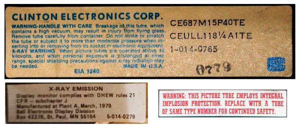
Needless to say, extreme caution is needed when working around the monitor, due to the high voltage that is present. The high voltage circuitry can be tested by holding an oscilloscope probe a couple inches away from the flyback transformer; even at that distance, a strong signal shows up on the oscilloscope. The CRT tube also poses a danger due to the vacuum inside; if the tube breaks, it can violently implode, sending shards of glass flying. Finally, X-rays are generated by using high voltage to accelerate electrons from a cathode to hit a target, just like a CRT operates, so there is a risk of X-ray production. To guard against this, the glass screen of a CRT contains pounds of lead to shield against radiation (which makes CRT disposal an environmental problem). In addition, the monitor's circuitry guards against overvoltages that would produce excessive X-rays. The photo below shows some of the safety warnings from the monitor.

Safety warnings on the Alto monitor. CRTs pose danger from implosion, X-rays, and high voltage.

Safety warnings on the Alto monitor. CRTs pose danger from implosion, X-rays, and high voltage.

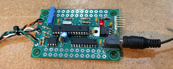
Since we don't have the Alto computer running yet, we can't use it to generate a video signal. Fortunately we obtained a display test board from Keith Hayes at the Living Computer Museum in Seattle. This board, based on a PIC 24F microcontroller, generates video, horizontal, and vertical signals to produce a simple test bar pattern on the display. We used this board to drive the monitor during testing.

Test board from the Living Computer Museum to drive the Alto's monitor.

Test board from the Living Computer Museum to drive the Alto's monitor.

We got a bit confused about which signal from the test board was the horizontal sync and which signal was the video. When we switched the signals around, we got a buzzing noise out of the monitor (see the video). Since the horizontal sync signal drives the high voltage power supply, we were in effect turning the power supply on and off 60 times a second with an audible effect. We eventually determined that Keith's test board was wired correctly and undid our modifications.

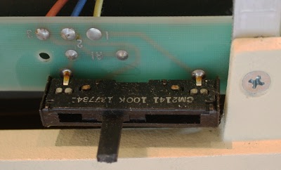
Even with the test board hooked up properly, the display didn't seem to be operational. But by turning off the room lights, we could see very faint bars on the display. We discovered that the monitor's brightness adjustment was flaky; just touching caused the display to flicker. Removing the variable resistor (below) and cleaning it with alcohol improved the situation somewhat. We tested an electrolytic capacitor in the brightness circuit and found it was bad, but replacing it didn't make much difference.

The brightness control on the Alto monitor. This control was flaky and needed cleaning.

The brightness control on the Alto monitor. This control was flaky and needed cleaning.

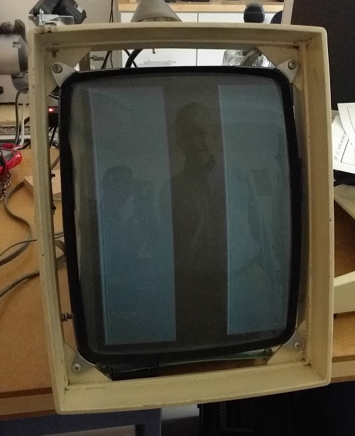
At the end of our session, we had dim bars on the display, showing that the display works but not at the desired brightness. We suspect that the CRT tube is weak due to its age, so we're searching for a replacement tube. Another alternative is rejuvenation – putting high-current pulses through the tube to get the "gunk" off the cathode, extending the tube's lifetime for a while. (If anyone has a working CRT rejuvenator in the Bay Area, let us know.)

The monitor successfully displays the test bars, but very faintly.

The monitor successfully displays the test bars, but very faintly.

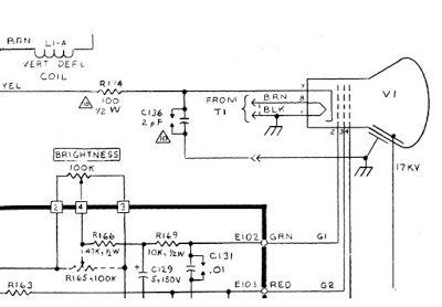
Our work on the monitor was greatly aided by the detailed service manual. If you want more information on how the monitor works, the manual has a detailed function description and schematics. An excerpt of the schematic is shown below.

Detail of the schematic diagram for the Alto's monitor, showing the CRT.

Detail of the schematic diagram for the Alto's monitor, showing the CRT. The schematic is online in the manual.

The disk controller

Our previous episode of Alto restoration ended with the surprising discovery that the Alto had the wrong disk controller card which wouldn't work with our Alto's Diablo disk drive. Fortunately, we were rescued by Al Kossow, who happened to have an extra Alto disk interface card lying around (that's Silicon Valley for you) and gave it to us. Below is a photo of the Alto disk interface card we got from Al. At the left is the edge connector that plugs into the Alto's backplane. The disk cable attaches to the connector on the right.

The Alto II Disk Control card, the interface to the Diablo drive.

The Alto II Disk Control card, the interface to the Diablo drive.

Conclusion

Our efforts to get the monitor working were moderately successful. Although the monitor is dim, it functions well enough to proceed with restoring the Alto. We'll see if we can improve the brightness or obtain a new CRT tube. We will probably work on the disk drive next, as the drive is necessary for booting up the Alto. Since the drive is a complex mechanical device with precise tolerances, I expect a challenge.