The PocketBeagle is a tiny but powerful inexpensive key-fob-sized open source Linux computer. It has 44 digital I/O pins, 8 analog inputs, and supports multiple serial I/O protocols, making it very useful as a controller. In addition, its processor includes two 200-MHz microcontrollers that allow you to implement low-latency, real-time functions while still having the capabilities of a Linux system This article discusses my experience trying out different features of the PocketBeagle, along with some technical details.

You may be familiar with the BeagleBone, a credit-card sized computer. The PocketBeagle is very similar to the BeagleBone, but smaller and cheaper. Both systems use TI's 1GHz "Sitara" ARM Cortex-A8 processor, but the PocketBeagle's I/O is stripped-down with 72 header pins compared to 92 on the BeagleBone. The PocketBeagle doesn't have the BeagleBone's 4GB on-board flash; all storage is on a micro-SD card. The BeagleBone's Ethernet and HDMI ports are also dropped.
The PocketBeagle uses an interesting technology to achieve its compact size—it is built around a System-In-Package (SIP) device that has multiple dies and components in one package (see diagram below). The Octavo Systems OSD3358-SM combines the TI 3358 Sitara processor, 512MB of RAM, power management and EEPROM. 1 In the photo above, this package has a white label and dominates the circuit board.

Initializing the SD card
To use the PocketBeagle, you must write a Linux file system to a micro-SD card. The easiest way to do this is to download an image, write it to the SD card from your computer, and then pop the SD card into the PocketBeagle. Details are in the footnotes.2
You can also compile a kernel from scratch, set up U-boot, and build a file system on the SD card. the PocketBeagle. There's a bunch of information on this process at Digikey's PocketBeagle getting started page. This is the way to go if you want flexibility, but it's overkill if you just want to try out the PocketBeagle.
Starting up the PocketBeagle
Unlike the BeagleBone, which supports a keyboard and an HDMI output, the PocketBeagle is designed as a "headless" device that you ssh into. You can plug the PocketBeagle into your computer's USB port, and the PocketBeagle should appear as a network device: 192.168.6.2 on Mac/Linux and 192.168.7.2 on Windows (details). You should also see a flash-drive style file system appear on your computer under the name "BEAGLEBONE". If the PocketBeagle has the default Debian OS3, you can log in with:
ssh [email protected]
Password: temppwd
Connecting to the PocketBeagle's serial console
While ssh is the simplest way to connect to the PocketBeagle, if anything goes wrong with the boot or networking, you'll need to look at the serial console to debug the problem.
The easiest solution is a UART Click board4, which gives you a serial connection over USB. You can then connect with "screen" or other terminal software: screen /dev/cu.usbserial\* 115200

You can also use a FTDI serial adapter such as the Adafruit FTDI Friend. (If you've worked with the BeagleBone, you may have one of these already.) You'll need three wires to hook it up to the PocketBeagle; it won't plug in directly as with the BeagleBone. Just connect ground, Rx and Tx between the PocketBeagle and the adapter (making sure to cross Rx to Tx).5

Pinout
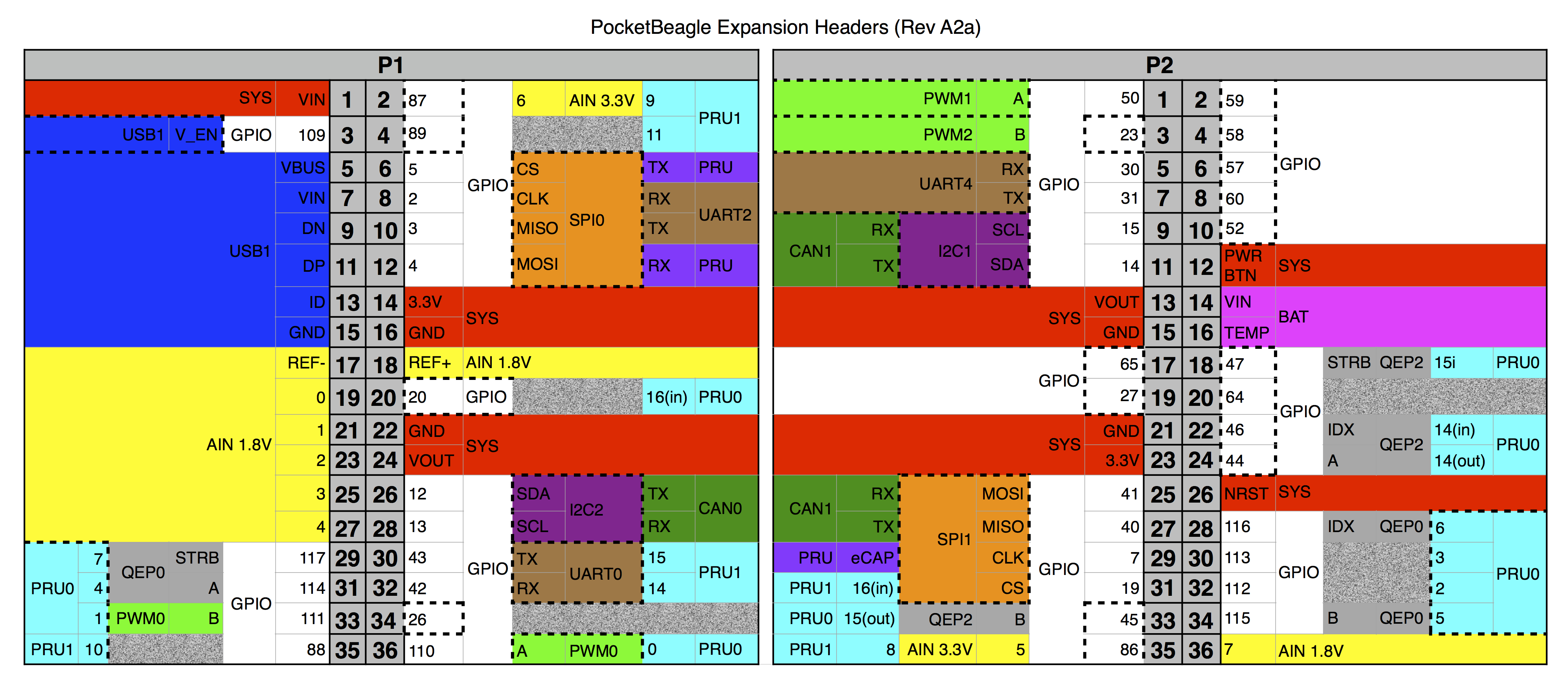
The PocketBeagle has two headers that provide access to I/O functions. (These headers are different from the BeagleBone's headers, so BeagleBone "capes" won't work with the PocketBeagle.) The PocketBeagle pinout diagram (below) shows what the header pins do. The diagram may seem confusing at first, since each pin has up to three different functions shown. (Most pins actually support 8 functions, so more obscure functions have been omitted.) The diagram is color coded. Power and system pins are labeled in red. GPIO (general-purpose I/O) pins are white. USB pins are blue. Analog inputs are yellow. UART serial pins are brown. PRU microcontroller pins are cyan. Battery pins are magenta. I2C bus is purple. PWM (pulse width modulation) outputs are light green. SPI (Serial Peripheral Interface) is brown. CAN (Controller Area Network) is dark green. QEP (quadrature encoder pulse) inputs are gray.9 The dotted lines in the diagram indicate the default pin functions (except for the PRU pins, which default to GPIO).6

Note that the diagram shows the headers from the component side of the board, not the silkscreened side of the board. Comparing the pin diagram with the board (below), you will notice everything is flipped horizontally. E.g. GPIO 59 is on the right in the diagram and on the left below. So make sure you're using the right header!

One tricky feature of the Sitara processor is that each pin has up to eight different functions. The motivation is that the chip supports a huge number of different I/O functions, so there aren't enough physical pins for every desired I/O. The solution is a pin mapping system that lets the user choose which functions are available on each pin. 7 If you need to change a pin assignment from the default, the config-pin command will modify pin mappings. (Some examples will be given below.) Pins can also be configured at boot time using a "U-Boot overlay".8
GPIO
The PocketBeagle exposes 45 GPIO (general purpose I/O) pins on the headers. The pins can be easily controlled by writing to pseudo-files. For example, the following shell code repeatedly blinks an LED connected to GPIO 11110 (which is accessed through header pin P1_33).
echo out > /sys/class/gpio/gpio111/direction
while :; do
> echo 1 > /sys/class/gpio/gpio111/value; sleep 1
> echo 0 > /sys/class/gpio/gpio111/value; sleep 1
> done

PRU
One of the most interesting features of the PocketBeagle is its PRUs, two 32-bit RISC microcontrollers that are built into the Sitara processor chip. These microcontrollers let you perform time-critical operations (such as "bit-banging" a protocol), without worrying about context switches, interrupts, or anything else interfering with your code. At the same time, the ARM processor gives high performance and a complete Linux environment. (I've made use of the BeagleBone's PRU to interface to a vintage Xerox Alto's 3 Mb/s Ethernet.)
Although the PRUs are not as easy to use as an Arduino, they can be programmed in C, using the command line or Texas Instruments' CCS development environment. I've written about PRU programming in C before (link) and the underlying library framework (link) for the 3.8.13 kernel, but since then much has changed with the way the PRUs are accessed. The PRUs are now controlled through the remoteproc framework. In addition, a messaging library (RPMsg) makes it simpler to communicate between the PRUs and the ARM processor. A "resource_table.h" file provides setup information (such as the interrupts used).
The following code will turn the LED on (by setting a bit in control register 30), wait one cycle (5ns), turn the LED off, and wait again. Note that the PRU output is controlled by modifying a bit in register R30. This will blink the LED at 40Mhz, unaffected by any other tasks, context switches or interrupts. (For the full code and details of how to run it, see my github repository.)
void main(void)
{
  while (1) {
    __R30 = __R30 | (1<<1); // Turn on output 1
    __delay_cycles(1);
    __R30 = __R30 & ~(1<<1); // Turn off output 1
    __delay_cycles(1);
  }
}
This code uses PRU0 output 1, which is accessed through header pin P1_33 (the same pin as the earlier GPIO example). Since this pin defaults to the GPIO, it must be switched to a PRU output:11
config-pin P1_33 pruout
This LED example illustrates two key advantages of using the PRU versus controlling a GPIO pin from Linux.12 First, the PRU code can operate much faster. Second, the GPIO code will produce an uneven signal if the CPU is performing some other Linux task. If you can handle milliseconds of interruption, controlling GPIO pins from Linux is fine. But if you need exact cycle-by-cycle accuracy, the PRU is the way to go.
Networking
Unlike the BeagleBone, the PocketBeagle doesn't have a built-in Ethernet port. However, there are several options for connecting the PocketBeagle to the Internet, described in the PocketBeagle FAQ. I found the easiest was to use WiFi via a WiFi adapter plugged into USB, as shown below. An alternative is to share your host computer's Ethernet, which I found more difficult to get working.14 Finally, you can add an Ethernet interface to the PocketBeagle using the expansion headers.

USB
You can easily connect USB devices to the PocketBeagle since the PocketBeagle has pins assigned for a second USB port. Plug a USB Micro-B breakout board into the Pocket Beagle as shown below, connect a USB OTG host cable and your USB port should be ready to go. Note that this USB port is a host (i.e. a USB device is connected to the PocketBeagle) opposite from the onboard USB port which works as a client (the PocketBeagle is connected as a device to another computer).

For instance, you can plug in a flash drive. (In the picture below, note that the flash drive is almost as big as the PocketBeagle.) The lsusb command will show your device, and then you can mount it with sudo mount /dev/sda1 /mnt.
 to the PocketBeagle.")
Analog inputs
The PocketBeagle has 8 analog input pins. Six of them take an input from 0 to 1.8V, while two take an input from 0 to 3.3V. (Be careful that you don't overload the input.)
The analog input value (between 0 and 4095) can be read from the file system as shown below. Change the number in voltage0 to select the input. (Inputs 5 through 7 require special handling.15)
$ cat /sys/bus/iio/devices/iio:device0/in_voltage0_raw
2510
In the photo below, I hooked up a light sensor (CdS photocell in a voltage divider) to provide a voltage to analog input 0 (header pin P1_19). The reference voltages come from header pins P1_17 (analog ground) and P1_18 (analog reference 1.8V). More light on the sensor produces a higher voltage, yielding a higher value from the input.

I2C / SPI
The PocketBeagle supports two SPI ports and two I2C ports. These serial protocols are popular for controlling chips and other devices.
 can be connected to the PocketBeagle's I2C port with four wires.")
For example, the photo above shows a cheap I2C accelerometer board connected to the PocketBeagle's SPI port.
Simply wire the power, ground, SCL (clock) and SDA (data) between the accelerometer and the PocketBeagle's I2C1 port (i.e. header P2 pins 13, 15, 9, 11). Probing for I2C devices with i2cdetect will show that the device uses address 68. The device can be turned on with i2cset and the registers dumped out with i2cdump to obtain acceleration values.16

Conclusion
The PocketBeagle is a low-cost, compact Linux computer, able to control external devices with its I/O ports and GPIO pins. Since the PocketBeagle was released recently, there isn't a whole lot of documentation on it. Hopefully this article has shown you how to get started with the PocketBeagle and use some of its features.
New (12/2017): The PocketBeagle System Reference Manual has lots of useful information, so take a look.
For more information, see the PocketBeagle FAQ and Getting Started pages. Also remember that the PocketBeagle uses the same processor and Linux kernel as the BeagleBone, so most of the information on the BeagleBone will carry over to the PocketBeagle. I've found the book Exploring BeagleBone to be especially helpful. Thanks to Robert Nelson and DigiKey for giving a PocketBeagle tutorial at Hackaday Superconference.
Follow me on Twitter or RSS to find out about my latest blog posts.
Notes and references
-
The Octavo package reminds me a bit of the Solid Logic Technology (SLT) modules that IBM used in the 1960s instead of integrated circuits. They consisted of small metal packages containing semiconductor dies and resistors connected together on a ceramic wafer, and were used in computers such as the IBM 360.
Two IBM SLT modules, with a penny for scale. Each module contains semiconductors (transistors or diodes) and printed resistors wired together, an alternative to integrated circuits. -
On a Mac, I used the following procedure to write the SD card. First, download an image from beagleboard.org. I use "Stretch IoT (non-GUI) for BeagleBone and PocketBeagle via microSD card". Then unmount the SD drive and format it as FAT-32. (Replace XXX below with the right drive number; don't format your hard disk!)
diskutil list
diskutil umountdisk /dev/diskXXX
sudo diskutil eraseDisk FAT32 BEAGLE MBRFormat /dev/diskXXX
sudo diskutil unmount /dev/diskXXXs1
Then write the disk image to the SD card:zcat /tmp/pocketbeagle.img | sudo dd of=/dev/diskXXX bs=2m xzcat *.xz | sudo dd of=/dev/diskXXX
Writing the image took about 10 minutes with a USB to micro-SD adapter. (If it's taking hours, I recommend a different USB adapter.) When done, install the SD card in the PocketBeagle. ↩ -
I'm using Debian with kernel
Linux beaglebone 4.14.0-rc8 #1 Mon Nov 6 15:46:44 UTC 2017 armv7l GNU/Linux. If you use a different kernel (such as 3.8.13), many of the software features will be different. ↩ -
One interesting feature of the PocketBeagle is its headers have the right pinout to support many mikroBUS boards. This is an open standard for small boards (similar to capes/shields), using a 16-pin connector. Hundreds of "click boards" are available for connectivity (e.g. Bluetooth, WiFi, Ethernet, NFC), sensors (e.g. pressure, temperature, proximity, accelerometer, seismic), security coprocessors, GPS, electronic paper, storage, and many more functions. The PocketBeagle doesn't officially support mikroBUS, but many boards "just work" (details). ↩
-
For the FTDI serial connection, connect Gnd to P1_22, Rx to P1_30 (UART0 Tx) and Tx to P1_32 (UART0 Rx). ↩
-
The PocketBeagle device tree file specifies the default pin mappings and names other pin mappings. But if you want to track down the actual hardware meaning of each header pin, it's complicated. The PocketBeagle schematic shows the mapping from header pins to balls on the Octavo chip package. The Octavo OSD335x documentation gives ball map to the Sitara chip. The Sitara AM335x datasheet lists the up to eight functions assigned to each pin. The Technical Reference Manual Section 9.3.1.49 describes the control register for each pin. Thus, it's possible but tedious to determine from "first principles" exactly what each PocketBeagle header pin does. ↩
-
There are a couple problems you can encounter with pin mapping. First, since not all chip pins are exposed on PocketBeagle headers, you're out of luck if you want a function that isn't wired to a header. Second, if you need two functions that both use the same pin, you're also out of luck. Fortunately there's enough redundancy that you can usually get what you need. ↩
-
The PocketBeagle uses U-Boot The U-Boot overlay is discussed here. For more information on device trees, see Introduction to the BeagleBone Black device tree. ↩
-
The Technical Reference Manual is a 5041 page document describing all the feature of the Sitara architecture and how to control them. But for specifics on the AM3358 chip used in the BeagleBone, you also need to check the 253 page datasheet. ↩
-
Note that there are two GPIO numbering schemes; either a plain number or register and number. Each GPIO register has 32 GPIOs. For example, GPIO 111 is in register 3 and also known as GPIO 3.15. (3*32+15 = 111) ↩
-
To switch P1_33 back to a GPIO, use
config-pin P1_33 gpio.Internally,
config-pinwrites to a pseudo-file such as/sys/devices/platform/ocp/ocp:P1_33_pinmux/stateto cause the kernel to change the pin's configuration. ↩ -
You can control GPIO pins from a PRU. However, there will be several cycles of latency as the control signal is delivered from the PRU to the GPIO. A PRU pin on the other hand can be read or written immediately. ↩
-
WiFi on the PocketBeagle is easy to set up using a command line program called
connmanctl. Instructions on configuring WiFi withconnmanctlare here and also are listed in the /etc/network/interfaces file. (Don't edit that file.) When I started upconnmanctl, it gave an error about VPN connections; I ignored the error. I tested WiFi with a Mini USB WiFi module and an Ourlink USB WiFi module. ↩ -
Sharing an Internet connection with the PocketBeagle isn't as simple as I'd like. To share with Windows, I followed the instructions here and here. (Note that BeagleBone instructions should work for the PocketBeagle.) I haven't had much luck with MacOS. In any case, I recommend connecting to the serial console first since there's a good chance you'll lose any SSH connection while reconfiguring the networking. ↩
-
Analog input pins 5 and 6 are shared with a GPIO pin via a voltage divider. To use one of these inputs, you must configure the shared GPIO as an input with no pullup/down so it won't affect the analog value. In addition, the input voltage is divided by 2 (so these pins can support up to 3.3V instead of 1.8V).
# Analog input 5 (P2_35)
$ config-pin P2_35 gpio
$ echo in > /sys/class/gpio/gpio86/direction
$ cat /sys/bus/iio/devices/iio:device0/in_voltage5_raw
# Analog input 6 (P1_2)
$ config-pin P1_2 gpio
$ echo in > /sys/class/gpio/gpio87/direction
$ cat /sys/bus/iio/devices/iio:device0/in_voltage6_raw
Analog input 7 (P2_36) is multiplexed by the power management IC (PMIC). It supports a maximum voltage of 1.8V. To read the value, you must first configure the PMIC:
$ sudo i2cset -y -f 0 0x24 9 5
$ cat /sys/bus/iio/devices/iio:device0/in_voltage7_raw
↩ -
In the accelerometer example, the board is approximately vertical with the chip's X axis pointing up. The X, Y, and Z accelerations returned by
i2cdumpin the screenshot were 0x42a8, 0x02dc, and 0x1348. These are signed values, scaled so 16384 is 1G. Thus, the X acceleration was approximately 1 G (due to Earth's gravity) while the other accelerations were small. These values change if the board's orientation changes or the board is accelerated. The temperature is 0xed10, which according to the formula in the register map yields 22.3°C or 72°F. The last three words are the gyroscope values, which are approximately 0 since the board isn't rotating. For more details on the accelerometer board see the register map, the datasheet and this Arduino post. ↩
 and printed resistors wired together, an alternative to integrated circuits.")
9 comments:
Thanks Ken, I always appreciate and value your expert opinion.
Thanks Ken! One comment though: on the Mac, you don't have to perform an erase disk. The last line containing dd alone would be good enough as dd overwrite the entire volume. Also, it'd be way faster using raw disk (rdiskXXX instead of diskXXX). Therefore, below are enough to umount, erase & write the image to the SD card on a Mac (note the r in rdiskXXX in of of dd) :
diskutil umountdisk /dev/diskXXXs1
xzcat *.xz | sudo dd of=/dev/rdiskXXX bs=4m
I want to express my thanks as well. I just purchased a PocketBeagle and I'm finding this post to be an excellent practical help in getting started with it. I greatly appreciate your posting the references to the Sitara AM3358.
I've been seduced by Allwinner H3-based linux boards (e.g. Orange Pi; so cheap! so many options!) but there's always been something deeply seductive about the PRCs on the TI chips... Thanks for the heads-up; $25 is a decent price
I believe the URL for the reference manual should be http://www.ti.com/lit/ug/spruh73p/spruh73p.pdf rather than http://www.ti.com/lit/ug/spruh73n/spruh73n.pdf.
Thanks, Paul. Apparently TI handles versioning for their documents by breaking all the old links.
If you use this link http://www.ti.com/lit/pdf/SPRUH73 It will always give you the latest version.
FedEx man came in just before lunch with my PocketBeagle. Fast forward to booting in the Beagle with a fresh Debian image. The START.HTM page says you can browse to http://beaglebone.local — turns out I could use the same address for SSH, i.e, ssh beaglebone.local. Shouldn't need to choose either 192.168.7.2 or 192.168.6.2 depending on your OS
Thanks for your great Beagle Bone information! Your posts on the PRU in particular have helped me get an application using them up and running. What are your thoughts on the new remoteproc interface vs. the older UIO interface? I found that even though the remoteproc interface seems to be what TI recommends now, using the older UIO interface and writing everything in assembly actually turned out to be less of a headache in my case. Also, do you know if the C compiler work with the older UIO interface or just remoteproc?
Thanks,
-Hunter
Post a Comment