One key point of this article is that there are three different ways to interpret the same IR signal and turn it into a hex code. Understanding these three ways will allow you to get codes from different sources and understand them correctly.
The IR transmission of the code
When you press a button on a Sony remote control, an infrared signal is transmitted. This transmission consists of a 40kHz signal which is turned on and off in a particular pattern. Different buttons correspond to different codes, which cause the signal to be turned on and off in different patterns.
The following waveform shows the IR code transmitted for STOP on my Sony CD remote control (RM-DC335). When the signal is high, a 40 kHz IR signal is transmitted, and when the signal is low, nothing is transmitted. In other words, the signal is actually rapidly turning on and off when it appears to be on in the figure. (The IR receiver demodulated the signal, so you don't see the 40 kHz transitions.)

A Sony IR signal starts with 2400 microseconds on and 600 microseconds off; that's the first wide pulse.
A "1" bit is transmitted with 1200 microseconds on and 600 microseconds off, while a "0" bit is transmitted with 600 microseconds on and 600 microseconds off. (This encoding is also called SIRC or SIRCS encoding.)
You may notice the "on" parts of the waveform appear wider than the "off" parts, even when both are supposed to be 600 microseconds. This is a result of the IR receiver, which switches on faster than switching off.
The above waveform represents one transmission of a 12-bit code. This transmission is normally repeated as long as the button is held down, and a minimum of three times. Each transmission starts 45ms after the previous one started. The Sony protocol also supports 15 and 20 bit codes, which are the same as above except with more bits.
For more information on the low-level transmission of Sony codes, see sbprojects.net.
Three ways to interpret the codes
The Sony encoding seems straightforward, but there are several different ways the signal can be interpreted. I will call these official decoding, bit decoding, and bit-1 decoding. Different sources use any of these three, which can cause confusion. I will explain these three decodings, using the previous waveform as an example.Official decoding
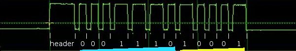
The "official" Sony protocol views the 12-bit code as 7 command bits and 5 address or device bits, transmitted least-significant-bit first (i.e. "backwards"). The device bits specify the type of device receiving the code, and the command bits specify a particular command for this device. In this example, the device bits (yellow) are 10001 when read right-to-left, which is 17 decimal. The command bits (blue) are 0111000 when read right-to-left, which is 56 decimal. The device value 17 corresponds to a CD player, and the command 56 corresponds to the STOP command (details).
Sony 15 bit codes are similar, with 7 command bits and 8 device bits. Sony 20 bit codes have 7 command bits, 5 device bits, and 8 extended device bits.
Bit decoding
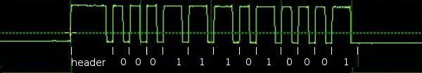
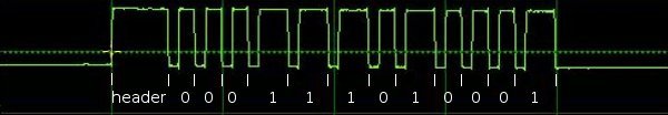
Many IR decoders just treat the signal as a sequence of bits, most-significant-bit first. I will call this bit decoding. Applying this interpretation to the above code, the code is interpreted as 0001 1101 0001 binary, or 1d1 hex, or 465 in decimal. Note that the last bit doesn't really consist of 1200 microseonds on and 600 microseconds off; it consists of 1200 microseconds on followed by a lot of time off. In other words, the transmission is off for 600 microseconds and then continues to be off until the next code is transmitted.
An alternative but equivalent interpretation is to view the code as a 2400 microsecond header, followed by 12 bits, where each bit is off then on (rather than on then off). A "1" bit is 600 microseconds off and 1200 microseconds on, while a "0" bit is 600 microseconds off and 600 microseconds on. This yields the same value as before (232 decimal), but avoids the special handling of the last bit.
Bit-1 decoding
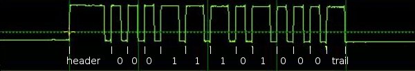
Many IR decoders drop the last bit, which I will call bit-1 decoding. Because the last bit doesn't end nicely with 600 microseconds off, some IR decoding algorithms treat the signal as 11 bits of data, ending with 600 microseconds on as a trailer. In this interpretation, the above code is 000 1110 1000 binary, or 0e8 hex, or 232 decimal. (Note that doubling this value and adding 1 yields the previous decoding of 465.)
Discussion
Is the code really 17/44 or 465 or 232? The official decoding is "right" in the sense that it is what the manufacturer intends. In addition, it reveals the internal structure of the code and the codes make more sense. For instance, the buttons 1-9 have consecutive codes with the official decoding, but not with the others. The other decodings are fine to use as long as you're consistent; the main thing is to understand that different sources use different decodings. My Arduino library uses the second bit decoding interpretation. The different decodings can be converted from one form to another with binary arithmetic.
Getting codes from a remote
Probably the easiest way to get the codes for your device is to use your existing remote control and see what codes it transmits. You can use my Arduino IR library to do the decoding, with the IRrecvDump demo program. Take a 3-pin IR decoder, hook it up to an Arduino, and then you can read the values for each button press on the serial port.Alternatively, you can look at the transmitted codes with an oscilloscope. For the diagrams above, I used an IR receiver module connected to two resistors (to drop the voltage), connected to the line input of my PC. I used the Zeitnitz Soundcard Oscilloscope program to display the signal. This lets you see exactly what is being transmitted, but you will need to stare at the screen, write down a bunch of 0's and 1's, and convert the binary value to get your codes.
Getting codes from LIRC files
The best source for IR codes that I've found is the Linux Infrared Remote Control project (lirc.org), which has a huge collection of config files for various remotes. (LIRC also includes a large collection of device drivers for many types of IR input/output hardware, and a software library.)The LIRC config file format is documented at WinLIRC, but I will walk through some examples.
Bit decoding
The RM-S530 LIRC file treats the codes as 12 bits long, using what I call bit decoding:
begin remote

  name  Sony
  bits           12
  flags SPACE_ENC|CONST_LENGTH
  eps            30
  aeps          100

  header       2470   557
  one          1243   556
  zero          644   556
  gap          45076
  min_repeat      2
  toggle_bit      0


      begin codes
          sleep                    0x0000000000000061
          cd_stop                  0x00000000000001D1
...
This file indicates that each entry is 12 bits long. A header consists of on for 2470 microseconds and off for 557 microseconds. A one bit consists of on for 1243 microseconds and off for 556 microseconds. A zero bit consists of on for 644 microseconds and off for 556 microseconds. Codes are repeated a minimum of 2 more times, with a gap of 45076 microseconds from start to start as the codes are constant length (CONST_LENGTH).
You may be wondering why these time values don't match the official values of 2400, 1200, and 600 microseconds. First, the LIRC data is generally measured from actual remotes, so the real-world timings don't quite match the theory. Second, IR sensors have some lag in detecting "on" and "off", and they typically stretch out the "on" time by ~100 microseconds, shortening the "off" time equally.
The LIRC file then lists the hex code associated with each button. For example the CD STOP code is hex 1D1, which is the same value as described earlier.
Bit-1 decoding
The LIRC file for the RM-D302 remote treats the codes as 11 bits and a trailing pulse. This is what I call the bit-1 decoding:
begin remote

  name  RM-D302
  bits           11
  flags SPACE_ENC|CONST_LENGTH
  eps            30
  aeps          100

  header       2367   638
  one          1166   637
  zero          565   637
  ptrail       1166
  gap          45101
  min_repeat      2
  toggle_bit      0


      begin codes
          cd_stop                  0x00000000000000E8
The key differences with the previous file are the ptrail field, indicating a trailing pulse of 1166 microseconds; and the bit count of 11 instead of 12. Note that the code value is different from the first file, even thought the IR transmission is exactly the same. The hex code 0E8 is the same as described earlier under bit-1 decoding.
Pre_data and post_data bits
Some LIRC files break apart the codes into constant pre_data bits, the code itself, and constant post_data bits. For instance, the file for my RM-D335 remote:
begin remote

  name  SONY
  bits            7
  flags SPACE_ENC
  eps            20
  aeps            0

  header       2563   520
  one          1274   520
  zero          671   520
  ptrail       1274
  post_data_bits  4
  post_data      0x8
  gap          25040
  min_repeat      2

      begin codes
          CONTINUE                 0x000000000000005C
...
          STOP                     0x000000000000000E
...
This file indicates that each code entry is 7 bits long, but there are also 4 post data bits. This means that after transmitting the 7 bits for the code, 4 additional bits are transmitted with the "post data" hex value 0x8, i.e. 1000 binary.
Putting this together the STOP button has the hex value 0E, which corresponds to the seven bits 000 1110. This is followed by four post data bits 1000, so the total transmission is the eleven bits 000 1110 1000, which is 0E8 hex, the same as before for the bit-1 decoding.
One more thing to notice in this LIRC file is it doesn't have the CONST_LENGTH flag, and the gap is 25ms instead of 45ms. This indicates the gap is from the end of one code to the start of the next, rather than from the start of one code to the start of the next. Specifying a gap between codes isn't how Sony codes are actually defined, it's close enough.
LIRC summary
Note that these LIRC files all indicate exactly the same IR transmission; they just interpret it differently. The first file defines the STOP code as 1D1, the second as E8, and the third as 0E.What does this mean to you? If you want to get a Sony code from a LIRC file and use it with the Arduino library, you need to have a 12 bit (or 15 or 20 bit) code to pass to the library (bit decoding). Look up the code in the file and extract the specified number of bits. If there are any pre_data or post_data bits, append them as appropriate. If the result is one bit short and the LIRC file has a ptrail value, append a 1 bit on the end to convert from bit-1 decoding to bit decoding. Convert the result to hex and you should have the proper code for your device, that can be used with the Arduino library.
Getting codes from hifi-remote.com
The most detailed site I've found on Sony codes specifically is hifi-remote.com/sony. An interesting thing about this site is it analyzes the structure of the codes. While the LIRC files just list the codes, the hifi-remote site tries to explain why the codes are set up the way they are.Note that this site expresses codes in Sony format, i.e. most-significant-bit first, and separating the device part of the code from the command part of the code. Also for a 20-bit Sony code, the 13 bit device code is expressed as a 5 bit value and an 8 bit value separated by a period. As a result, you may need to do some binary conversion and reverse the bits to use these codes.
To work through an example, I can look up the data for a Sony CD. There are multiple device codes, but assume for now I know my device code is 17. The table gives the code 56 for STOP. Convert 56 to the 7 bit binary value 0111000 and reverse it to get 0001110. Convert 17 to the 5 bit binary value 10001 and reverse it to get 10001. Put these together to et 000111010001, which is 1D1 hex, as before.
To work through a 20-bit example, if I have a Sony VCR/DVD Combo with a device code of 26.83, the site tells me that the code for "power" is 21. Convert 21 to a 7 bit binary value, 26 to a 5 bit binary value, and 83 to a 8 bit binary value. Then reverse and concatenate the bits: binary 1010100 + 01011 + 11001010, which is a8bca in hex. To confirm, the RMT-V501A LIRC file lists power as A8B with post_data of CA.
To use this site, you pretty much have to know the device code for your device already. To find that, obtain a code for your device (e.g. from your existing remote or from LIRC), split out and reverse the appropriate bits, and look up the device code on the site. Alternatively, there are only a few different device codes for a particular type of device, so you can just try them all and see what works.
This site also has information on "discrete codes". To understand discrete codes, consider the power button on a remote that toggles between "on" and "off". This may be inconvenient for automated control, since without knowing the current state, you don't know if sending a code will turn the device on or off. The solution is the "discrete code", which provides separate "on" and "off" codes. Discrete codes may also be provided for operations such as selecting an input or mode. Since these codes aren't on the remote, they are difficult to obtain.
Other sites
Additional config files are available at irremote.psiloc.com. These are in LIRC format, but translated to XML. The site remotecentral.com has a ton of information on remotes, but mostly expressed in proprietary formats.
31 comments:
Well, I'll test my understanding. Thanks for the wonderful work by the way, Arduino remote working well.
But let's say I wanted to submit something gleaned from your program back to the LIRC archive. (I've finally got something that can figure some of this out. Happy dance.)
So I have a Canon Projector, and I get NEC protocol codes from it. An actual response for VolumeUp was: "NEC: CF3906F"
Is this a reasonable header to be using if I submitted it back to LIRC? (I borrowed one of their NEC devices which had very slight speed differences.)
" name Canon LV-X1 Projector
bits 28
flags SPACE_ENC
eps 20
aeps 200
header 8800 4400
one 550 1650
zero 550 550
ptrail 550
repeat 8800 2200
gap 38500
toggle_bit 0
frequency 38000
"
Or have I messed up on counting the ptrail/number of bits?
Alan: that looks right except NEC codes are always 32 bits; the code is actually 0x0cf3906f and you should say "bits 32".
By the way, NEC codes have the interesting property that the second byte is the complement of the first, and the fourth byte is the complement of the third. That is, 0C is the complement of F3 and 90 is the complement of 6F. The point is, I can tell from the first F that the first byte is 0 (which doesn't get printed out but is still there).
Ken: Thanks for another very useful post, it clears up a number of things for me. It always seemed to me a rosetta stone for IR codes has been sorely needed.
The hifi-remote site appears to be the main resource for JP1 remote hacking. There is a windows utility called IRscope, and a decoding DLL. I think source for both are around but it takes some digging to find the source for decodeir.dll.
* http://www.hifi-remote.com/forums/viewtopic.php?t=11668
I haven't tried IR scope yet as I need to come up with some compatible hardware. I suspect an Arduino sketch could be made to be compatible with their IRwidget.
--Rob
While the Arduino might be all you really need for many IR projects, I couldn't resist ordering a USB Infrared Toy which is a DangerousPrototypes project. It's based on a PIC instead of an AVR/Arduino. It has an IRman compatible mode that will be useful with LIRC and similar software.
Related to your sony ir code visualization, it works with the open source SUMP logic analyzer client
Since the SUMP protocol is documented, Arduino sketch to speak SUMP should be doable. Someone probably has already done it.
When my USB IR Toy arrives I'll post a review.
Hope This Helps,
--Rob
Hi Ken,
I recently used your excellent IRremote library on a Teensy board. I ended up hacking the code a bit, mostly to add support for using other timers (some Teensy boards don't have timer2), and supporting different timers on different boards. I'll attach the modified code. The changes are mostly added to IRremoteInt.h.
I tried to email you (sending the modified code), but it bounced. If you see this, please email me at paul at pjrc dot com.
Sony IR codes have been well documented since about 2001 in a paper I wrote at that time. It is on file at remotecentral.com in their files section. Look under my name barrygordon
Hi Ken, Your library is awesome and I would like to make a small contribution: I had to disable interrupts before send and enable after. Sending work great until I enable receiving. I'm using freeduino with receiver on pin 3 and sender on 2. Kind regards, Adi S
I actually gone through the whole exercise and generate some sony wave files using makehex etc.
http://www.unclebobtech.com/technical-details-for-those-who-want-to-creat
The arduino library would only return the combine of command + address as one word. One need to write a simple function to separate and decode it.
If you search for Barry Gordon at remotecentral take the "ProntoEdit's IR Display Format" document. At first I thought his sony-file is gone, but maybe it's this one.
Here is the direct link:
http://www.remotecentral.com/features/irdisp1.htm
I tried to control my Sony DAV-S500 which's Remote is the RM-SS800. If you want to use the codes written at http://lirc.sourceforge.net/remotes/sony/RM-SS800 then you have to do the following:
- Let's take the Code for "open/close": 0x4ba36
- It's a 19 bit "bit1" code as ken calls it -> so calculate x2 +1 = 0x9746d to obtain the 20 bit code.
- Take a look at the pulse lengths of one and zero in the document. Zero is long and one is short - it's read-out the other way around. If you want to use the code "0x9746d" then you'd have to swap the pulse lengths in "IRremoteInt.h" like
"#define SONY_ONE_MARK 600". I did this and it works.
- A nicer way is: take the complement: 0xfffff - 0x9746d = 0x68B92. This value you can send:
"irsend.sendSony(0x68b92, 20);" and it will work. =)
In binary this is "0110100 01011 10010010" so we get 22 for the command and 26 and 73 for the device code (remember: lsb is first). When you take a look at more commands this is a really nice view, because related commands have numbers near to each other and for a bunch of commands the device code is identical (this is for a home-theater so there is more than one device code).
Just beginning with the IR Library this took me a while to find out - I hope it's of use for someone =)
iSi
I am having troubles with trying to send Directv codes, on the ir code website its listed like below. I got the sony codes to work but they looked a lot different than this.
begin remote
name RC64
flags RAW_CODES
eps 30
aeps 100
gap 29920
begin raw_codes
name KEY_PAUSE
6050 1100 1250 1150 650 550 650 550 1250 1150 650 550
1200 600 600 550 650 1150 650
Hi Ken,
Credit to all your hard work on this and sharing it with everyone, very useful!
I have a couple of questions if you / anyone is still monitoring this page
At the end of the blog post it says additional config files hosted by psolic are lirc format translated to XML (something I was looking at doing for all remote types before I saw this) but looking at some of the files the first part is encoded and not an XML file as expected - any idea what that is? Presumably something they added in as it looks like it was (is?) a commercial product / app for Nokia phones that reads them. All the useful data and codes are there in plain text though.
Secondly I haven't seen any raw codes in the files at psolic.. You can record raw in lirc and using the arduion ir library but, and I haven't looked into it yet, I don't think the arduino ir library raw mode matches up with lirc raw mode? But is probably translatable.
Last of all, although it doesn't seem to explicitly say in the ir library code, would the arduino ir library work on an arduino micro or even a (clone) pro micro based on the 32u4 (available at robotshop)? Looking for the smallest pre-made board that supports the library to use as an emitter.
Thanks!
This are the lirc-codes for the DBox2.
How can i use this for the arduino and your library?
"#
# this config file was derived from the DBOX config file
#
# brand: Nokia
# model: ?
# supported devices: D-Box2
#
begin remote
name D-BOX2
bits 8
flags SHIFT_ENC|CONST_LENGTH
eps 10
aeps 300
header 510 2520
one 450 550
zero 450 550
pre_data_bits 1
pre_data 0x0
post_data_bits 8
post_data 0xC5
gap 59500
repeat_bit 0
begin codes
power 0x00000000000000CF
home 0x00000000000000FB
d-box 0x000000000000001B
1 0x000000000000007F
2 0x00000000000000BF
3 0x000000000000003F
4 0x00000000000000DF
5 0x000000000000005F
6 0x000000000000009F
7 0x000000000000001F
8 0x00000000000000EF
9 0x000000000000006F
0 0x00000000000000FF
blue 0x0000000000000023
yellow 0x00000000000000B5
green 0x0000000000000055
red 0x000000000000004B
ok 0x00000000000000F3
vol_+ 0x0000000000000097
vol_- 0x0000000000000017
mute 0x00000000000000EB
right 0x000000000000008B
up 0x000000000000008F
down 0x000000000000000F
next 0x00000000000000D5
prev 0x0000000000000035
left 0x000000000000000B
help 0x00000000000000BE
end codes
end remote
begin remote
name D-BOX2
bits 8
flags SHIFT_ENC|CONST_LENGTH
eps 10
aeps 300
header 510 2520
one 450 550
zero 450 550
pre_data_bits 1
pre_data 0x0
post_data_bits 8
post_data 0x0
gap 40000
repeat_bit 0
begin codes
_D-BOX_ 0x0000000000000080
end codes
end remote"
Thanks
haii,,all,,am currently trying to decode the blue star ac remote.What i have learnt till now ,based on that i could say,during my testing i got a 48 bit pulse.the first 32 bit is some what similar to NEC protocol,but i am not able able to crack it down the last 12 bits.Basically in that 12 bit ,the last 8 bit is the inversion of the preceding 8 bit.Could any body give some information about on what grounds they are generating the last 12 bit.
I have been trying to use LIRC on a raspberry pi to control my entertainment system. I have been able to mimic all my remotes except the remote for the DVR. This is a Time Warner Samsung SMT-H3272. The remove is a UR5U-8780L. It seems that when the remote switches to the cable box it no longer sends out either SONY or NEC codes. In fact the signals seem to be rather random in looking at the response from mode2. Does anyone have any ideas on where to look for a solution?
I am new to Infrared.
I have a device with Infrared. How do I know the commands supported by that device?
How to send commands to Device and read the response?(please share sample code or tutorials)
Thanks
Hi Ken, I'm trying to make a timed mute control for my sony bravia TV, I've managed to record the IR signal but cant for the life of me work out how much of the code I need to send to the TV to mute it. The IR sender is working, I can see it pulse using my camera, but all of my combinations fail, can you please help. Here is the data stream.
OFF ON
53988 usec, 2380 usec
540 usec, 620 usec
580 usec, 600 usec
560 usec, 1200 usec
560 usec, 600 usec
580 usec, 1180 usec
560 usec, 600 usec
580 usec, 600 usec
560 usec, 1200 usec
560 usec, 600 usec
560 usec, 600 usec
580 usec, 600 usec
560 usec, 600 usec
25820 usec, 2380 usec
560 usec, 620 usec
560 usec, 600 usec
560 usec, 1200 usec
560 usec, 600 usec
580 usec, 1180 usec
560 usec, 620 usec
560 usec, 600 usec
560 usec, 1180 usec
580 usec, 600 usec
560 usec, 600 usec
580 usec, 580 usec
580 usec, 600 usec
25800 usec, 2400 usec
540 usec, 620 usec
560 usec, 600 usec
580 usec, 580 usec
580 usec, 600 usec
25820 usec, 2380 usec
540 usec, 620 usec
560 usec, 620 usec
560 usec, 1180 usec
580 usec, 580 usec
580 usec, 1200 usec
560 usec, 600 usec
560 usec, 600 usec
580 usec, 1180 usec
580 usec, 580 usec
580 usec, 600 usec
560 usec, 600 usec
580 usec, 580 usec
25820 usec, 2380 usec
580 usec, 600 usec
560 usec, 600 usec
580 usec, 1180 usec
560 usec, 600 usec
580 usec, 1180 usec
580 usec, 580 usec
580 usec, 600 usec
560 usec, 1180 usec
580 usec, 600 usec
580 usec, 600 usec
560 usec, 600 usec
560 usec, 600 usec
25820 usec, 2380 usec
540 usec, 620 usec
580 usec, 600 usec
560 usec, 1180 usec
580 usec, 600 usec
580 usec, 1180 usec
560 usec, 600 usec
580 usec, 580 usec
580 usec, 1180 usec
580 usec, 580 usec
580 usec, 600 usec
580 usec, 600 usec
560 usec, 600 usec
25820 usec, 2380 usec
540 usec, 620 usec
580 usec, 580 usec
580 usec, 1180 usec
580 usec, 600 usec
560 usec, 1200 usec
560 usec, 600 usec
560 usec, 600 usec
580 usec, 1180 usec
560 usec, 600 usec
580 usec, 600 usec
560 usec, 600 usec
580 usec, 580 usec
25820 usec, 2400 usec
560 usec, 600 usec
560 usec, 600 usec
580 usec, 1180 usec
560 usec, 620 usec
560 usec, 1180 usec
560 usec, 620 usec
560 usec, 600 usec
560 usec, 1180 usec
580 usec, 600 usec
560 usec, 620 usec
560 usec, 600 usec
560 usec, 600 usec
int IRsignal[] = {
// ON, OFF (in 10's of microseconds)
238, 54,
62, 58,
60, 56,
120, 56,
60, 58,
118, 56,
60, 58,
60, 56,
120, 56,
60, 56,
60, 58,
60, 56,
60, 2582,
238, 56,
62, 56,
60, 56,
120, 56,
60, 58,
118, 56,
62, 56,
60, 56,
118, 58,
60, 56,
60, 58,
58, 58,
60, 2580,
240, 54,
62, 56,
60, 58,
58, 58,
60, 2582,
238, 54,
62, 56,
62, 56,
118, 58,
58, 58,
120, 56,
60, 56,
60, 58,
118, 58,
58, 58,
60, 56,
60, 58,
58, 2582,
238, 58,
60, 56,
60, 58,
118, 56,
60, 58,
118, 58,
58, 58,
60, 56,
118, 58,
60, 58,
60, 56,
60, 56,
60, 2582,
238, 54,
62, 58,
60, 56,
118, 58,
60, 58,
118, 56,
60, 58,
58, 58,
118, 58,
58, 58,
60, 58,
60, 56,
60, 2582,
238, 54,
62, 58,
58, 58,
118, 58,
60, 56,
120, 56,
60, 56,
60, 58,
118, 56,
60, 58,
60, 56,
60, 58,
58, 2582,
240, 56,
60, 56,
60, 58,
118, 56,
62, 56,
118, 56,
62, 56,
60, 56,
118, 58,
60, 56,
62, 56,
60, 56,
60, 0};
I've recentlt retired and trying to get into some of this stuff as a past time, the end use will be, press mute, then 3 mins later the signal is automatically re sent to restore audio, avoiding the commercials :)
Bob
can i get remote codes for model RM-Y 194 i found it everywhere but i didnt get.... plzzz help
i just want power ,volume , channel up/down codes
ok, let's see if i understand this correctly: A.B = device code, C = command. take binary representation of each, reverse the string. then add zeros (if necessary) to make A 5 bits, B 8 bits, and C 7 bits. then concatenate in this order: C + A + B. then convert that into hex. is that right?
Hi Ken,
Can't get the NEC send to work, when I decode I get:
0xFF807F
If I look at the raw codes below I would assume it's suppose to be:
0x1FE00FF01
{8900 ,4500 ,500 ,600 ,500 ,600 ,500 ,650 ,500 ,600 ,450 ,650 ,500 ,650 ,450 ,650 ,450 ,650 ,500 ,1700 ,500 ,1750 ,500 ,1750 ,450 ,1750 ,500 ,1750 ,450 ,1750 ,450 ,1750 ,500 ,1750 ,500 ,1750 ,450 ,650 ,450 ,650 ,500 ,600 ,500 ,650 ,450 ,650 ,450 ,650 ,450 ,700 ,450 ,650 ,450 ,1750 ,500 ,1750 ,450 ,1750 ,500 ,1750 ,500 ,1700 ,500 ,1750 ,450 ,1750 ,500};
Maybe you can shed som light?
Best regards,
/R
Hi Ken. Thanks for your awesome library. I'm using it to control several units in my home.
Now I'm working on reverse-engineering the protocol for my daikin heat pump (which uses some unkown protocol) and to do so I need an oscilloscope. So I figured I'll save some money and build one that uses the soundcard of my PC and Zeitnitz' Soudcard Scope.
Can you give some details about how you implemented the circuit you hooked up to your soundcard?
Is it as simple as limiting the voltage output of an IR receiver diode (non-modulated receiver) and then somehow connect that to a mini-jack cable and plug it in to the soundcard?
Are there any tricks here to minimize noise etc?
I was trying to mc gyver a remote control for a tiny sony hi-fi set (cmt ne3) using arduino and your great library, but none of the codes I found worked: I just needed the code for the "source" button, which is the only way to select the aux input channel (you can't from the front panel)and the remote controller got lost. So I brute-forced the whole 12bit word while staring at the set display, and I found that it responds to codes with the device code 00001 bin (which is supposed to be for televisions).
I then brute forced the 7 bit op code only, finding the following map, in decimal:
3=sleep
35=set clock
36=vol+
56=memory
82=cd
83=clock
84=power
98=tape
100=vol-
105=display
120=radio
Obiously something is missing, including what I was looking for, so I proceeded brute forcing the whole 15bit word (it took more than one hour to the poor Arduino Uno) and I found that it was among the 15bit code with device code = 00000001. I didn't jot down the map because the AUX mode got toogled during the brute force procedure, so I just let it so! What I learnt:
1)it is better to use the brute force than looking for the codes via internet: believe it or not is less time consuming, unless you don't find something for your exact model and brand (and I hope what I wrote will be useful to somebody else)
2) the same unit might be taking 12bit words for some functions and 15 bit words for others...
Sorry, mistake: the 8 bit device code for the 15bit word I found is:
00001001 or 09 in hex
Hi Ken,
On my Samsung aircon remote, the current status is displayed in the remote. It seems that if I go outside and change settings, then come back and hit one button, that the unit is in synch with the remote. How is that done?
Marius
Great tutorial!
I have several "legacy" receivers that I want to control on my Android phone, using LIRC and an lirc-client.
I built a simple IR transmitter using an IR diode, pull-up, and logic level FET. It works fine controlling my Kenwood using the RC-R0900 device file I found on the LIRC site.
But, I'm having no luck with my Sony STR-985, even though the decoded signal transmitted by the LIRC setup looks the same on the oscope as what I see when I use the Sony remote.
The remote is a RM-PG411. There's a RM-PP411 device file on the LIRC website. The sony manual seems to say either remote will work with the STR-DE985 but the "PP" device doesn't work. The code for KEY-POWER doesn't match what I record on the oscope, nor what several sites indicate KEY-POWER should be (21 or 0x15)
I have an IR demodulator chip in another project, so I used it to capture the baseband signal from the RM-PG411 remote. The device code is 16, and the KEY_POWER I decode matches what I see from remote centrals device file for Sony 16 device (0x15)
So, I created a new LIRC file with the KEY_POWER definition, but the receiver doesn't recognized it. On the oscope, the demodulated signal looks identical to what I get when using the actual remote (the actual remote works fine).
I thought maybe signal strength was marginal, but I capture the signal fine even when the diode isn't aimed at the transceiver.
I coded a simple script that transmits the KEY_POWER, sleeps 5 seconds and repeats forever. I run this script while trying to position the IR diode very close to the receivers IR window, far away, and everything in between. The receiver never responds.
The receiver responds to the actual remote when it is held directly in front of the window, or when it's several feet awan not aimed directely at the receiver. So, it's not like the amplitude of the transmitted IR signal is critical.
I'm using 40000 for the frequency in the LIRC file, and 1200, 600 for the timings instead of what were probably learned values in the LIRC PP device file.
I'm running out of things to try---any suggestion would be appreciated. I could post the scope traces of the remote and the LIRC transmitted signal, if someone feels like helping out.
Figured it out!
Turns out the remote sends the command three times. I hadn't set the time base on the oscope slow enough to see more than the first transmission.
I just added "min_repeat 2", and it now works.
Your blog mentioned that was in the LIRC file you referenced, but I didn't realize it was critical to have the command sent three times. I was thinking it was something for a key like volume up or volume down, where you really wanted the equivalent of pushing the button multiple times.
Hi Dave! I'm glad you figured out the problem. Yes, Sony devices often require the code sent multiple times. Sometimes they are sensitive to how much time is in between the repeats, so watch out for that.
Many thanks!
Hugely useful for converting Sony codes into the 15 bit hex required for use in ESPHome, especially for codes that the controllers don't emit (e.g. explicit power on and power off commands). Enormously valuable and, as far as I can tell, the only resource on the internet that provides this information. As others have said, Sony remotes send the command more than once and a single send doesn't cut the mustard (which had me head scratching for a few mins), but a simple fix to sort. Many, many thanks!
Post a Comment