The first programming language for the Xerox Alto was BCPL, the language that led to C.
This article shows how to write a BCPL "Hello World" program using Bravo, the first WYSIWYG text editor, and run it on the Alto simulator.
The Xerox Alto is the legendary minicomputer from 1973 that helped set the direction for personal computing.
Since I'm helping restore a Xerox Alto (details), I wanted to learn more about BCPL programming.
(The influential Mesa and and Smalltalk languages were developed on the Alto, but those are a topic for another post.)
The Xerox Alto II XM computer. Note the video screen is arranged in portrait mode. Next to the keyboard is a mouse. The Diablo disk drive is below the keyboard. The base contains the circuit boards and power supplies.
Using the simulator
Since the Alto I'm restoring isn't running yet, I ran my BCPL program on Salto, an Alto simulator for Linux written by Juergen Buchmueller.
To build it, download the simulator source from
github.com/brainsqueezer/salto_simulator,
install the dependencies listed in the README,
and run make.
Then run the simulator with the appropriate Alto disk image:
bin/salto disks/tdisk4.dsk.Z
Here's what the simulator looks like when it's running:
The Salto simulator for the Xerox Alto.
(To keep this focused, I'm not going to describe everything you can run on the simulator,
but I'll point out that pressing ? at the command line will show the directory contents.
Anything ending in .run is a program you can run, e.g. "pinball".)
Type bravo to start the Bravo text editor.
Press i (for insert).
Enter the BCPL program:
// Hello world demo
get "streams.d"
external
[
Ws
]

let Main() be
[
Ws("Hello World!*N")
]
Here's a screenshot of the Bravo editor with the program entered:
A Xerox Alto 'Hello World' program for written in BCPL, in the Bravo editor.
Press ESC to exit insert mode.
Press p (put) to save the file.
Type hello.bcpl (the file name) and press ESC (not enter!).
Press q then ENTER to quit the editor.
Run the BCPL compiler, the linker, and the executable by entering the following commands at the prompt:
bcpl hello.bcpl
bldr/d/l/v hello
hello
If all goes well, the program will print "Hello World!"
Congratulations, you've run a BCPL program.
Output of the Hello World program in BCPL on the Xerox Alto simulator.
The following figure explains the Hello World program.
If you know C, the program should be comprehensible.
'Hello World' program in BCPL with explanation.
The BCPL language
The BCPL language is interesting because it was the grandparent of C.
BCPL (Basic Combined Programming Language)
was developed in 1966. The B language was developed in 1969 as a stripped down version of BCPL by Ken Thompson and Dennis Ritchie. With the introduction of the PDP-11, system software needed multiple datatypes, resulting in the development of the C language around 1972.
Overall, BCPL is like a primitive version of C with weirdly different syntax.
The only type that BCPL supports is the 16-bit word, so it doesn't use type declarations.
BCPL does support
supports C-like structs and unions, including structs that can access
bit fields from a word. (This is very useful for the low-level systems programming tasks that BCPL was designed for.)
BCPL also has blocks and scoping rules like C, pointers along with lvalues and rvalues, and C-like looping constructs.
A BCPL program looks strange to a C programmer because many of the special characters are different and BCPL often uses words instead of special characters. Here are some differences:
Blocks are defined with [...] rather than {...}.
For array indexing, BCPL uses a!b instead of a[b].
BCPL uses resultis 42 instead of return 42.
Semicolons are optional, kind of like JavaScript.
For pointers, BCPL uses lv and rv (lvalue and rvalue) instead of & and *.
rvalues.
The BCPL operator => (known as "heffalump"; I'm not making this up) is used for indirect structure references instead of C's ->.
selecton X into, instead of C's switch, but cases are very similar with fall-throughs and default.
lshift and rshift instead of << and >>.
eq, ne, ls, le, gr, ge in place of ==, !=, <, <=, >, >=.
test / ifso / ifnot instead of if / else.
A BCPL reference manual is here if you want all the details of BCPL.
More about the Bravo editor
The Bravo editor was the first editor with WYSIWYG (what you see is what you get)
editing. You could format text on the screen and print the
text on a laser printer.
Bravo was written by Butler Lampson and Charles Simonyi in 1974. Simonyi later moved to Microsoft, where he wrote Word, based on the ideas in Bravo.
Steve Jobs saw the Alto when he famously toured Xerox Parc in 1979, and it inspired the GUI for the Lisa and Mac.
However, Steve Jobs said in a commencement address,
"[The Mac] was the first computer with beautiful typography. If I had never dropped in on that [calligraphy] course in college, the Mac would have never had multiple typefaces or proportionally spaced fonts. And since Windows just copied the Mac, it's likely that no personal computer would have them."
This is absurd since the Alto had a variety of high-quality proportionally spaced fonts in 1974, before the Apple I was created, let alone the Macintosh.
The image below shows the Hello World program with multiple fonts and centering applied.
Since the compiler ignores any formatting, the program runs as before.
(Obviously styling is more useful for documents than code.)
The Bravo editor provides WYSIWYG formatting of text.
The manual for Bravo is here but
I'll give a quick guide to Bravo if you want to try more editing.
Bravo is a mouse-based editor, so use the mouse to select the text for editing.
left click and right click under text to select it with an underline.
The editor displays the current command at the top of the editing window.
If you mistype a command, pressing DEL (delete) will usually get you
out of it.
Pressing u provides an undo.
To delete selected text, press d.
To insert more text, press i, enter the text, then ESC to exit insert mode.
To edit an existing file, start Bravo from the command line,
press g (for get), then enter the filename and press ESC.
To apply formatting, select characters, press l (look), and then enter a formatting code
(0-9 to change font, b for bold, i for italics).
Troubleshooting
If your program has an error, compilation will fail with an error message. The messages don't make much sense, so try to avoid typos.
The simulator has a few bugs and tends to start failing after a few
minutes with errors in the simulated disk.
This will drop you into the Alto debugger, called Swat.
At that point, you should restart the simulator. Unfortunately any files you created in the simulator will be lost when you exit the simulator.
If something goes wrong, you'll end up in Swat, the Xerox Alto's debugging system.
Conclusion
The BCPL language (which predates the Alto) had a huge influence on programming languages since it led to C (and thus C++, Java, C#, and so forth).
The Bravo editor was the first WYSIWYG text editor and strongly influenced personal computer word processing.
Using the Alto simulator, you can try both BCPL and Bravo for yourself by compiling a "Hello World" program, and experience a slice of 1970s computing history.
How does a tiny chip time the runners in the Bay to Breakers race? In this article, I take die photos of the RFID chip used to track athletes during the race.
Bay to Breakers is the iconic San Francisco race, with tens of thousands of runners (many in costume and some in nothing) running 12km across the city.
To determine their race time, each runner wears an identification bib.
As you can see below, the back of the bib has a small foam rectangle with a metal foil antenna and a tiny chip underneath. The runners are tracked using a technology called RFID (Radio Frequency Identification).
The bib worn by runners in the Bay to Breakers race. At the top, behind the foam is an antenna and RFID chip used to detect the runner at the start and end of the race.
At the beginning and end of the race, the runners cross special mats that
contain antennas and broadcast ultra high frequency radio signals.
The runner's RFID chip detects this signal and sends back the athlete's ID number, which is programmed into the chip.
By tracking these ID numbers, the system determines the time each runner took to run the race.
The cool thing about these RFID chips is they are powered by the received radio signal; they don't need a battery.
Mylaps, whose name appears on the foam rectangle, is a company that supplies sports timing systems: the bibs with embedded RFID chips, the detection mats, and portable detection hardware.
The detection system is designed to handle large numbers of runners, scanning more than 50 tags per second.
Removing the foam reveals an unusually-shaped metal antenna, the tiny RFID chip (the black dot above the word "DO", and the barely-visible word "Smartrac".
Studying the Smartrac website reveals that this chip is the
Impinj Monza 4 RFID chip, which operates in the 860-960 MHz frequency range and is recommended for sports timing.
The RFID circuit used to detect runners in the Bay to Breakers. The metal forms an antenna. The tiny black square in the center is the RFID chip.
Getting the chip off the bib was a bit tricky. I softened the bib material in Goof Off, dissolved the aluminum antenna metal with HCl and removed the adhesive with a mysterious BGA adhesive solvent I ordered from Shenzhen.
The chip itself is remarkably tiny, about the size of a grain of salt. The picture below shows the chip on a penny, as seen through a microscope: for scale, a grain of salt is by the R and the chip is on the U (in TRUST).
This is regular salt, by the way, not coarse sea salt or kosher salt.
I spent a lot of time trying to find the chip when it fell on my desk, since it is practically a speck.
The RFID chip used to identify runners is very small, about the size of one of the letters on a penny. A grain of salt (next to R) and the RFID chip (next to U).
In the picture above, you can see the four round contact points where the chip was connected to the antenna.
There's still a blob of epoxy or something around the die, making it hard to see the details.
The chip decapsulation gurus use
use boiling nitric and sulfuric acids to remove epoxy, but I'm not that hardcore so I heated the chip over a stove flame. This burned off the epoxy much better than I expected, making the die clearly visible as you can see in the next photo.
I took 34 die photos using my metallurgical microscope and stitched them together to get a hi-res photo. (I described the stitching process in detail here). The result is the die photo below (click it for the large image).
Surprisingly, there is no identifying name or number on the chip.
However, comparing my die photo with the picture in the
datasheet confirms that the chip is the Monza 4 RFID chip.
I can identify some of the chip's layout, but the chip is too dense and has too many layers for me to reverse engineer the exact details.
Thus, the description that follows is slightly speculative.
Die photo of the Impinj Monza 4 RFID chip.
The four pins in the corners are where the antenna is connected. (The chip has four pins because two antennas can be used for improved detection.)
The left part of the chip is the analog logic, extracting power from the antenna, reading the transmitted signal, and modulating the return signal.
The rectangles on the left are probably transistors and capacitors forming a charge pump to extract power from the radio signal (see patent 7,561,866).
The right third of the chip is so-called "random logic" that carries out the commands sent to the chip. According to the datasheet, the chip uses a digital logic finite state machine, so the chip probably doesn't have a full processor.
The 32 orderly stripes in the middle are the non-volatile memory (NVM).
Above the stripes, the address decode circuitry is barely visible. The chip has 928 bits of storage (counting up the memory banks on the datasheet) so I suspect the memory is set up as a 32x29 array.
Some NVM details are in patent 7307534.
Along the lower and right edges of the chip, red lines are visible; these connect chips together on the wafer for testing during manufacturing (patent 7307528).
The Impinj Monza 4 RFID chip on top of a 8751 microcontroller chip shows that the RFID chip is very small and dense.
To show how small the chip is, and how technology has changed, I put the RFID chip on top of an 8751 microcontroller die. The 8751 microcontroller is a chip in Intel's popular 8051 family dating from 1983. Note that the circuitry on the RFID chip is denser and the chip is much, much smaller.
(The photo looks a bit photoshopped, but it genuinely is the RFID chip sitting on the surface of the 8751 die. I don't know why the RFID chip is pink.)
So, if you ran in the Bay to Breakers, that's the chip that tracked your time during the race.
(There aren't a lot of other RFID die photos on the web, but a few are at
Bunnie Studios,
Zeptobars and ExtremeTech if you want to see more.)
A few days ago, I wrote about how I'm helping restore a Xerox Alto for Y Combinator.
This new post describes the first day of restoration: how we disassembled the computer and disk drive and fixed a power supply problem, but ran into a showstopper problem with the disk interface.
The Xerox Alto was a revolutionary computer from 1973, designed by computer pioneer Chuck Thacker at Xerox PARC
to investigate ideas for personal computing.
The Alto was the first computer built around a mouse and GUI, as well as introducing Ethernet and laser printers to the world.
The Alto famously inspired Steve Jobs, who used many of its ideas in the Lisa and Macintosh computer.
Alan Kay, whose vision for a personal computer guided the Alto, recently gave an Alto computer to Y Combinator.
Getting this system running again is a big effort but fortunately I'm working with a strong team, largely from the IBM 1401 restoration team. Marc Verdiell, Luca Severini, Ron, Carl Claunch, and I started on restoration a few days ago, as shown in Marc's video below.
Disassembling the Alto
We started by disassembling the computer.
The Xerox Alto has a metal cabinet about the size of a dorm mini-fridge, with a Diablo hard disk drive on top, and a chassis with power supplies and the circuit boards below. With some tugging, the chassis slides out of the cabinet on rails as you can see in the photo below. At the front are the four cooling fans, normally protected by a decorative panel.
Note the unusual portrait layout of the display.
The Xerox Alto II XM 'personal computer'. The card cage below the disk drive has been partially removed. Four cooling fans are visible at the front of it.
With the chassis fully removed, you can see the four switching power supplies on the left, the blue metal boxes. The computer's circuit boards are on the right, not visible in this picture.
The wiring for the backplane is visible at right front, with pins connected by wire-wrapped wire connections. This wiring connects the circuit boards together.[1]
The Alto's chassis has been removed. On the left are the four switching power supplies (blue boxes). On the right, the connections for the wire-wrapped backplane are visible. The circuit boards plug into this backplane.
The power supplies
Our first goal was to make sure the power supplies worked after decades of sitting idle.
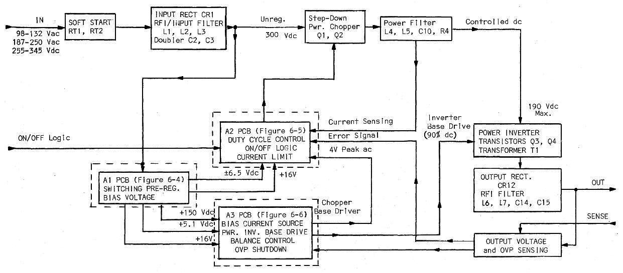
The Alto uses high-efficiency switching power supplies.[2]
To explain the power supplies in brief, input power is chopped up thousands of times a second to produce a regulated voltage. Unlike modern computer power supplies, there's a second switching stage (the inverter), which drops the voltage to the desired 15 volts.
This was more complexity than I expected, but
fortunately the detailed power supply manual was available online, thanks to Al Kossow's bitsavers.[3]
We tested each power supply with a resistor as a dummy load and checked that the output voltage was correct. We also used an oscilloscope to make sure the output was stable.
All the power supplies worked fine, except for the +15V supply (top center), which had trouble getting up to 15 volts and staying there.
We disassembled the faulty power supply to track down the problem.
The photo of the power supply below shows how densely components are crammed into the power supply. Two of the circuit boards have been removed and are at the back. Note the three large filter capacitors at the front.
Switching power supply from the Xerox Alto computer. Two of the control boards have been removed and are visible at back.
We noted signs of overheating on the AC connector, as well as a somewhat sketchy looking repair (a trace replaced by a wire) and some signs of corrosion. Apparently the power supply had problems in the past and had been serviced. We cleaned up the corrosion and it appeared to be superficial.
The power supply disassembled easily for repair, as you can see below.
The main board is at the right.
The tower of three inductors on the main board is an unusual way of mounting inductors.
Three circuit boards (top) plug into the main board. Because the power supply uses discrete components instead of a modern SMPS control IC, it needs a lot of control circuitry.
The switching transistors (lower center) are mounted onto metal heat sinks for cooling.
The Alto's switching power supply, disassembled. The main board is in the lower right. The three circuit boards are at top, below the large input capacitors.
The large capacitors were attached with screws, making it easy to remove them for testing.
A capacitance meter showed that the three large capacitors had failed, explaining why the power supply had trouble outputting the desired voltage.
Ron went off and found replacement capacitors, although they weren't an exact match for the originals. With the new capacitors mounted in place, the power supply worked properly.
Inside the Diablo disk drive
We also looked at the Diablo disk drive, which provides 2.5MB of storage for the Xerox Alto. The first step was removing the disk pack.
In normal operation, the front of the drive is locked shut to keep the disk from being removed during use.
To remove the disk without powering up the drive, we had to open the drive and manually trip the latch that locks it shut (see
Diablo drive manual).
This picture shows the disk pack being reinserted into the drive.
Unlike modern hard disk drives, the Alto's disk can be removed from the drive.
Users typically used different disks for different tasks — a programming disk, a word processing disk, and so forth.
The disk pack is a fairly large white package, resembling a cross between an overgrown Frisbee and a poorly-detailed Star Wars spaceship.
The drive's multiple circuit boards are also visible in the photo.[4]
Inserting a 2.5 MB hard disk pack into the Diablo drive used by the Xerox Alto computer.
As the disk pack enters the drive, it opens up to provide access to the disk surface.
The photo below shows the exposed surface of the disk, brownish from the magnetizable iron oxide layer over the aluminum platter.
The read/write head is visible above the disk's surface, with another head below the disk. The disk stores data in 203 concentric pairs of tracks, with the heads moving in and out together to access each pair of tracks.
Closeup of the hard disk inside the Diablo drive. The read/write head (metal/yellow) is visible above the disk surface (brown).
Although the heads are widely separated during disk pack insertion, they move very close to the disk surface during operation,
floating about one thousandth of a millimeter above the surface.
The diagram below from the manual helps visualize this minute distance, and illustrates the danger of particles on the disk's surface.
The Diablo disk and why contaminants are bad, from the Alto disk manual.
The disk interface cliffhanger
The final activity of the day was making sure all the Alto's circuit boards were in the right slots and the cables were all hooked up properly.[5]
Everything went smoothly until I tried to hook up the Diablo disk drive to the disk interface card: the disk drive cable didn't fit on the card's connector!
The cable to the Alto disk didn't fit onto the disk interface card!
After trying various combinations of cables and edge connectors,
we discovered that the rainbow-colored ribbon cable you can see in the lower right above did fit the disk interface card. But instead of going to the Diablo disk drive, this cable went to a connector on the back of the Alto labeled "Tricon".
Tricon is the controller for the Trident Disk, a high-capacity disk drive that could be used with the Alto, providing 80 MB instead of the just 2.5 MB that the standard Diablo drive provides.
Looking at the disk interface card more closely, we saw it was labeled "Alto II Trident Disk Interface" (upper left corner of the photo below), confirming that it was for the Trident.
Trident Disk Interface card for Xerox Alto computer. (See label in upper left.)
It was a shock to discover the disk interface card was for the Trident drive, since our Alto has
the standard Diablo drive, which is completely incompatible with the Trident.[6]
We checked all the boards and verified that the system was missing the Diablo interface board.
This was a showstopper problem; with the wrong board, the disk drive would be unusable and we wouldn't be able to boot up the system.
What could we do? Network boot the Alto? Build a disk simulator? Find a Trident drive on eBay? (We actually found a Trident disk platter on eBay for $129, but no drive.)
Tune in next episode to find out what we did about the disk interface problem. (Spoiler: we found a solution thanks to Al Kossow.)
Notes and references
[1]
The physical layout of the power supplies is specified on page 11 of
the Alto documentation introduction.
On the top are three Raytheon/Sorensen power supplies, +12V (15A), +15V (12A), and -15V (12A).
At the bottom is a large LH Research Mighty Mite power supply providing +5V (60A) and -5V (12A).
Why the variety of voltages? Most of the circuitry in the Alto uses 5V, which is standard for TTL chips.
The MOS memory chips use +5V, -5V and +12V. The Ethernet card uses +15V and -15V, with +15V powering the transceiver. The disk drive uses +/- 15V.
[2]
Steve Jobs claimed that the Apple II's use of a switching power supply was a revolutionary idea
ripped off by other computer manufacturers. However, the Alto is just one of many computers that used switching
power supplies before Apple (details).
[3]
For full details on the power supply operation, see the
block diagram.
First, the 115V AC line input is converted to 300V DC by a rectifier and voltage doubler. (The voltage doubler is a clever way of supporting both 115V and 230V inputs; using the doubler with 115V. This is why older PCs have a switch on the power supply to select 115V or 230V. Modern power supplies handle a wide input range, and don't require a switch.)
Next, the power supply has a chopper, a PWM transistor circuit that chops up the 300V DC, producing a regulated 120V-200V DC, depending on the output load. This goes to the inverter, which drives a step-down/isolation transformer that produces the desired 15V output. A regulation circuit sends feedback to the chopper based on the output voltage. Meanwhile, an entirely separate switching power supply circuit generates voltages (including +150V) used by the power supply internally.
Modern power supplies use a single switching stage in place of the separate chopper and inverter. I believe the two stages were used to reduce the load on the bipolar switching transistors, which don't have the performance of modern MOSFET switching transistors. (As Ron pointed out, modern power supplies often have a PFC (power factor correction) stage for improved efficiency. Thus, the two-stage design has returned, although the stages are entirely different now.)
Modern power supplies use a power supply control IC. The Alto's power supply instead has control circuits built from simple components: transistors, op amps, 555 timers.
This is one reason the power supply requires three circuit boards.
[4]
The following table from the Alto disk manual gives the stats for the drive.
Statistics on the Diablo 31 disk used with the Xerox Alto computer.
[5]
The Alto backplane has 21 slots, not all of which are used in our system.
The list of which board goes into which slot is on page 8 of
the Alto documentation.
[6]
I suspect that the Y Combinator Alto originally had both a Trident drive and a Diablo drive (as well as four Orbit boards to drive a laser printer), and when it was taken out of service, the Trident drive, the Diablo interface board, and the Orbit boards went off somewhere else.
This left the Alto with a drive that didn't match the interface card.
For reference, schematics and documentation on the Trident interface board are here.
Despite all the chips on the disk interface board, it doesn't do very much, since each TTL chip is fairly simple.
The interface board has some counters, one word data buffers, parallel/serial conversion, and a bit of control logic.
The Alto was designed to offload many hardware tasks to microcode, so the hard work of disk I/O is performed in microcode (software).
Alan Kay recently gave his 1970's Xerox Alto to Y Combinator and I'm helping with the restoration
of this legendary system.
The Alto was the first computer designed around a graphical user interface
and introduced Ethernet and the laser printer[1]
to the world.
The Alto also was one of the first object-oriented systems, supporting the Mesa and Smalltalk languages.
The Alto was truly revolutionary when it came out in 1973, designed by computer pioneer Chuck Thacker.
Xerox built about 2000 Altos for use in Xerox, universities and research labs, but the Alto was never sold as a product.
Xerox used the ideas from the Alto in
the Xerox Star, which was expensive and only moderately successful.
The biggest impact of the Alto was in 1979 when Steve Jobs famously toured Xerox and saw the Alto and other machines.
When Jobs saw the advanced graphics of the Alto, he was inspired to base the user interfaces of the Lisa and Macintosh systems on Xerox's ideas, making the GUI available to the mass market.[2]
How did Y Combinator end up with a Xerox Alto? Sam Altman, president of Y Combinator has a strong interest in the Alto and its place in computer history. When he mentioned to Alan Kay that it would be fun to see one running, Alan gave him one.
This article gives an overview of the Alto, its impact, and how it was implemented.
Later articles will discuss the restoration process as we fix components that have broken over the decades and get the system running.
The Xerox Alto II XM computer. Note the video screen is arranged in portrait mode. Next to the keyboard is a mouse. The Diablo disk drive is below the keyboard. The base contains the circuit boards and power supplies.
The photo above shows Y Combinator's Alto computer.
The Alto has an unusual portrait-format display, intended to match an 8½" by 11" page of paper.
Most displays of the time were character-oriented, but the Alto had a bitmapped display, with each of the 606x808 pixels controllable independently. This provided unprecedented flexibility for the display and allowed WYSIWYG (what-you-see-is-what-you-get) editing.
The bitmapped display memory used almost half the memory of the original Alto, however
In front of the keyboard is the three-button mouse.
Xerox made the mouse a fundamental input device for the Alto and designed the user interface around the mouse.
The disk drive at the top of the cabinet takes a removable 2.5 megabyte disk cartridge. The small capacity of the disk was a problem for users, but files could also be accessed over the Ethernet from file servers.
The lower part of the cabinet contains the computer's circuit boards and power supplies, which will be discussed below.
Dynabook and the vision of the Alto
The motivation for the Alto was Alan Kay's Dynabook project.
In 1972, he wrote A Personal Computer for Children of All Ages, setting out his vision for a personal, portable computer for education (or business), with access to the world's knowledge.
In effect, Alan Kay presented a detailed vision for the touchscreen tablet decades before
it was practical.[3]
Alan Kay with a mockup of the Dynabook.
Although the Dynabook was proposed years before the necessary hardware was available, the ideas could be tried out on the Alto, an "interim Dynabook".
Photo by Marcin Wichary, CC BY 2.0.
The Dynabook (seen in mockup above) was to be a low-cost, battery-powered, portable computer with a touchscreen and graphics, able to access information over the network. The system would be highly interactive and programmable in an object-oriented language. As well as the keyboard, voice input could be used. Books could be downloaded and purchased.
Since the necessary hardware was science fiction when the Dynabook was proposed, the Alto was built as an "interim Dynabook" for research.
Butler Lampson's 1972 memo entitled "Why Alto" proposed using the Alto for research in distributed computing, office computing, graphics, and personal computing. He stated,
"If our theories about the utility of cheap,
powerful personal computers are correct, we should be able to demonstrate
them convincingly on Alto."
Xerox used the Alto to research and develop the ideas of personal computing.[4]
Software
The Alto had a large collection of software, largely implemented in the BCPL (predecessor to C), Mesa and Smalltalk languages.
The Bravo text editor (seen below) is considered the first WYSIWYG editor, with formatted text on the screen matching the laser printer output.
Also below is the Draw illustration program which used the mouse and an icon menu to create drawings.
Other significant programs included email, file transfer (FTP) and an integrated circuit editor.
The Alto also ran some of the first networked multiplayer games such as Alto Trek and Maze War.
Bravo was the word processor for the Xerox Alto, providing WYSIWYG text editing.
The Draw program for the Xerox Alto uses the mouse and icons for drawing.
The Alto simulator Salto was used for these images.
Hardware
The Alto was introduced in 1973.
To understand this time in computer hardware, the primitive 4004 microprocessor had been introduced a couple years earlier.
Practical microprocessors such as the 6502 and Z-80 were still a couple years in the future and the Apple II wouldn't be released until 1977.
At the time, minicomputers such as the Data General Nova and PDP-11 built processors out of hundreds of simple but fast TTL
integrated circuits, rather than using slow, unreliable MOS chips.
The Alto was built similarly, and is a minicomputer, not a microcomputer.[5]
The Alto has 13 circuit boards, crammed full of chips.
Each board is a bit smaller than a page of paper, about 7-5/16" by 10", and holds roughly 100 chips (depending on the board).
For the most part, the chips are bipolar TTL chips in the popular 7400 series.
(The MOS memory chips are an exception.)
The image below shows the Alto's card rack and some of the boards.
The Xerox Alto contains 21 slots for circuit boards. Each board is crammed with chips, mostly TTL.
The Alto's CPU consists of three boards.
The Control board is the heart of the processor: it manages the 16 microcode tasks and contains microcode in PROM.
The ALU board performs arithmetic and logic operations, and provides the main register storage.
The Control RAM board provides additional microcode storage in RAM and additional processor registers.
(Note that in a few years, a single chip microprocessor could replace these three boards.)
The photo below shows the ALU board. The 16-bit addition, subtraction and Boolean operations are performed by four of the popular 74181 ALU chip, used in many other processors of the era.
Each 16-bit register requires multiple chips for storage.
The 32x16 register file is historically interesting as it is built from i3101 64-bit bipolar memory chips, Intel's first-ever product.
The ALU board from the Xerox Alto.
The Alto came out at a time when memory was expensive and somewhat unreliable.[6]
In 1970, Intel introduced the first commercially available DRAM memory, the 1103 chip, holding 1 kilobit of storage and making
magnetic core memory obsolete.
The original Alto used 16 boards crammed full of these chips to provide 128 kilobytes of memory.
The Alto we have is a more modern Alto II XM (eXtended Memory) with 512 kilobytes of storage on four boards.
Even so, the limited memory capacity was a difficulty for programmers and users.
The photo below shows one of the memory board, packed with denser 16 kilobit chips.
A 128KB memory card from the Xerox Alto. It uses eighty 4116 memory chips, each with 16 kilobits of storage.
Microcode
The Alto hardware provides a simple micro-instruction set and uses
microcode to implement a full instruction set on top of this,[7]
including some very complex instructions.
The Alto introduced the
BITBLT graphics instruction, which draws an arbitrary bitmap to the display in a variety of ways (e.g. paint over, gray stipple or XOR).
"Blitting" became a standard graphics operation, still be found in Windows.
The Alto takes microcode further than most computers,
implementing many functions in microcode that most computers implement in hardware, making the Alto hardware simpler and more flexible.[8]
Microcode tasks copy every pixel to the display 30 times a second, refresh dynamic memory, read the mouse, handle disk operations, drive Ethernet — operations performed in hardware on most computers.
Much of the Alto microcode is stored in RAM, so languages or even user programs can run custom microcode.
Next steps
The first step to getting the system running will be to make sure the power supplies work and provide the proper voltages.
The Alto uses four complex but highly efficient switching power supplies: +15V, -15V, +12V, and +/-5V.[9]
(Most of the chips use +5V, but the memory chips and some interfaces require unusual voltages.)
The power supplies are mounted in the cabinet behind the card cage, as you can see in the photo below. The +/-5V supply is on the right, and the three other power supplies are on the left.
Looking into the back of the Alto, you can see the four switching power supplies (blue). The card cage is behind them. The disk drive has been removed from the top of the cabinet. On the back of the cabinet, connectors to the display, Ethernet, and other devices are visible.
Restoring this systems is a big effort but fortunately there's a strong team working on it, largely from the IBM 1401 restoration team. The main Alto restorers so far are Marc Verdiell, Luca Severini, Ron, and Carl Claunch. Major technical contributions have been provided by Al Kossow (who has done extensive Alto restoration work in the past and is at the Computer History Museum) and the two Keiths (who have restored Altos at the Living Computer Museum).
For updates on the restoration, follow kenshirriff on Twitter.[10]
Notes and references
[1]
The laser printer was invented at Xerox by Gary Starkweather and networked laser printers were soon in use with the Alto. Y Combinator's Alto is an "Orbit" model, with slots for the four boards that drive the laser printer, laboriously rendering 16 rows of pixels at a time.
[2]
Malcolm Gladwell describes Steve Jobs' visit to Xerox in detail in Creation Myth.
The article claims that Xerox licensed its technology to Apple, but strangely
that license wasn't mentioned in
earlier articles about Xerox's lawsuit against Apple.
The facts here seem murky.
[3]
Amazingly, Alan Kay even predicted ad blockers in his 1972 Dynabook paper:
"One can imagine one of the first programs an owner will write is a filter to eliminate advertising!"
I thought that Alan Kay missed WiFi in the Dynabook design, but as he points out in the comments, wireless networking was a Dynabook feature.
[4]
Xerox called the Alto "a small personal computing system", saying,
"By 'personal computer' we mean a non-shared system containing sufficient
processing power, storage, and input-output capability to satisfy the computational needs of a single user." (See ALTO: A Personal Computer System Hardware Manual.) Xerox's vision of personal computing is described in the retrospective Alto: A personal computer.
[5]
The Alto documentation refers to the microprocessor, but this
term describes the microcode processor.
The Alto does not use a microprocessor in the modern sense.
[6]
Since memory chips of the era were somewhat unreliable (especially in large quantities),
the Alto used parity plus 6 bits of error correcting code to improve reliability.
As well as the four memory boards, the Alto has three memory control boards to decode addresses and implement error correction.
[7]
The Alto's microcode instructions and "real" instructions (called Emulated Instructions) are
described in the Hardware Reference.
The Alto's instruction set is similar to the Data General Nova.
[8]
The Alto has 16 separate microcode tasks, scheduled based on their priority.
The Alto's microcode tasks are described in Appendix D of the Hardware Manual.
The display task illustrates how low-level the microcode tasks are.
In a "normal" computer, the display control hardware fetches pixels from memory.
In the Alto, the display task in microcode copies pixels from memory to the display hardware's 16 word pixel buffer as each line is being written to the display. The point is that the hardware is simplified, but the microcode task is working very hard, copying every pixel to the display 30 times a second.
Similarly the Ethernet hardware is simplified, since the microcode task does much of the work.
[9]
Steve Jobs claimed that the Apple II's use of a switching power supply was a revolutionary idea
ripped off by other computer manufacturers. However, the Alto is just one of many computers that used switching
power supplies before Apple (details).
[10]
Many sources have additional information on the Alto.
Bitsavers has a large collection of Alto documentation.
DigiBarn has photos and more information on the Alto.
The Computer History Museum has a large collection of Alto source code online here.
The Alto simulator Salto is available here if you want to try out the Alto experience.
Wikipedia has a detailed article on the Alto.


 and the RFID chip (next to U).")


. On the right, the connections for the wire-wrapped backplane are visible. The circuit boards plug into this backplane.")


 is visible above the disk surface (brown).")


")


. The card cage is behind them. The disk drive has been removed from the top of the cabinet. On the back of the cabinet, connectors to the display, Ethernet, and other devices are visible.")