The hardware
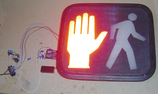
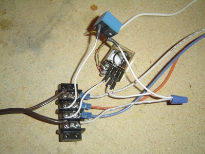
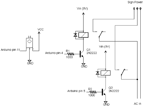
The pedestrian sign is controlled by two relays that switch 120-volt AC on and off; one powers the "walk" part of the sign, and one powers the "don't walk" part.
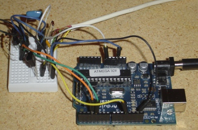
The Arduino drives the relays through transistors connected to 9-volt supply. Technically the relays are 12-volt relays, but they seem to work with 9 volts. I used one 10A relay, and one 5A relay, just because that's what I had around.
Needless to say, 120 volts can be dangerous, both to yourself and to your Arduino. Follow the appropriate precautions. I make no claims about the safety of this circuit.
The remote control input uses an IR detector module connected to the Arduino.
For details on the IR detection, see the article on my IRremote library. The code section below describes how to modify the code to support different remotes.
I found the IR detector didn't work super-reliably when the sign was turned on. This was probably due to high-frequency electrical interference since adding some capacitors helped, but the light itself could have been interfering. I probably should have wired up the relay circuit and the IR detector circuit farther apart to minimize interference, as I did when controlling a DC motor.
Inside the pedestrian sign
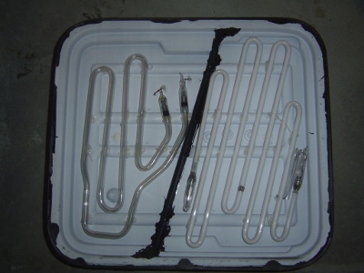
You may be curious about what's inside a pedestrian sign. What I have is the lighting unit; this goes inside the metal case that you see attached to a traffic pole. (In case you're worried, I didn't steal this from an intersection. I got it on ebay from some city that was replacing their units with more efficient LED units.)
Inside the signal are two neon tubes, roughly the shape of the hand and the pedestrian; generating red and white light respectively. I use "neon tube" in the generic sense; I don't know what gas is actually inside. Note that the tubes are not colored and the cover is clear; the red color is entirely from the gas discharge.
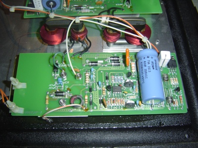
Beneath the tubes are two high-voltage driver circuits, one for each tube. Each driver circuit runs off 120V AC and has an oscillator (using a LM2903 comparator) driving a flyback transformer through a power transistor (under the board). This generates multi-kilovolts to drive the tubes. Note at the far left the standoffs that keep the output wire an inch above the circuit board due to the high voltage. Needless to say, I stay away from the circuitry while it is operating. Each driver board has a separate AC input; when AC is fed in, the tube lights up. One drawback of the driver circuitry is it makes a high-pitched whine when turned on. I originally planned to use the sign to indicate unittest pass/fail status, but it was too annoying to people nearby.
The code
The Arduino code is available at IRtraffic.pde and has two main functions: IR processing and light cycle processing.In the IR code, the IR remote is used to select one of five states: walk illuminated, blinking don't walk, don't walk illuminated, off, or cycling (which goes through the first three states). The IR functionality uses my IRremote library to decode the output from a remote control.
The code has the values for a particular remote control hard-coded. I used a Sony DVD remote:
#define OFF_CODE 0x1CB92 // Stop on Sony DVD remote
#define WALK_CODE 0xB92 // 1 on Sony DVD remote
#define BLINK_CODE 0x80b92 // 2 on Sony DVD remote
#define DONT_CODE 0x40b92 // 3 on Sony DVD remote
#define CYCLE_CODE 0x4CB92 // Play on Sony DVD remote
The first part of the
loop function calls the IR library to see if an IR signal has been decoded. If so, it switches to the appropriate mode. If an unexpected IR value is encountered, it is printed to the serial port.
void loop() {
  // Process the IR input, if any
  if (irrecv.decode(&results)) {
    if (results.value == WALK_CODE) {
      Serial.write("Walk\n");
      mode = MODE_WALK;
      cycle = false;
    }
    else if (results.value == DONT_CODE) {
      Serial.write("Don't walk\n");
      mode = MODE_DONT;
      cycle = false;
    }
    else if (results.value == OFF_CODE) {
      Serial.write("Off\n");
      mode = MODE_OFF;
      cycle = false;
    }
    else if (results.value == BLINK_CODE) {
      Serial.write("Blinking don't walk\n");
      mode = MODE_BLINK;
      blinkOn = true;
      nextBlinkMillis = millis() + 500; // 500 ms blink
      cycle = false;
    }
    else if (results.value == CYCLE_CODE) {
      Serial.write("Cycle\n");
      nextCycleMillis =  millis() + 5000; // delay 5 seconds
      cycle = true;
      mode = MODE_WALK;
    }
    else {
      Serial.print("unexpected value: ");
      Serial.println(results.value, HEX);
    }
    irrecv.resume(); // Resume decoding (necessary!)
  }
If you want to use a different remote, simply look at the "unexpected values" printed to the serial port while pressing the desired buttons, copy the hex values into the code, recompile, and reinstall. For instance, to use some Tivo buttons, simply change the button definitions to:
#define OFF_CODE 0x20df10ef
#define WALK_CODE 0xa10cd00f
#define BLINK_CODE 0xa10c8807
#define DONT_CODE  0xa10cc807
#define CYCLE_CODE 0xa10c6c03
The other main function of the code is timing. There are two timing cycles going on. First, if cycle mode is enabled, the mode is advanced through walk, blink, and don't walk every five seconds. Second, if in the blinking don't walk phase, the output is turned on or off every half second.
I originally used delays of 500 or 1000 ms for the timing, but this had the disadvantage that the light wasn't very responsive to the remote control - it would wait up to 1 second before processing the remote control value. I rewrote the code using the BlinkWithoutDelay approach. In this approach, there are no delays in the loop code. Instead, the millis() value is checked to see if it is time to change state. If nothing needs to be done, loop() ends without any delay.
In more detail, the boolean cycle is true if the light is to cycle between the three phases. In this case, nextCycleMillis is set to the time at which we move to the next cycle (i.e. 5 seconds in the future). Once we reach that time, the mode is advanced. The boolean blinkOn keeps track of whether the don't walk sign is on or off while blinking.
  if (cycle && millis() >= nextCycleMillis) {
    if (mode == MODE_WALK) {
      mode = MODE_BLINK;
      blinkOn = false;
      nextBlinkMillis = millis() + 500; // 500 ms blink
      nextCycleMillis = millis() + 5000; // delay 5 seconds
    }
    else if (mode == MODE_BLINK) {
      mode = MODE_DONT;
      nextCycleMillis =  millis() + 5000; // delay 5 seconds
    }
    else {
      mode = MODE_WALK;
      nextCycleMillis =  millis() + 5000; // delay 5 seconds
    }
  }
The other independent time is nextBlinkMillis. This is the time at which the don't walk sign should change state, and it is set 500ms into the future.
  if (mode == MODE_BLINK && millis() >= nextBlinkMillis) {
    blinkOn = !blinkOn;
    nextBlinkMillis = millis() + 500; // 500 ms blink
  }
The code may be confusing at first due to the two independent times (nextCycleMillis and nextBlinkMillis) and state variables (mode and blinkOn). It seemed simpler this way rather than folding both cycles into one.
Finally, the code sets the appropriate lights on or off:
  if (mode == MODE_WALK) {
    digitalWrite(DONT_PIN, LOW);
    digitalWrite(WALK_PIN, HIGH);
  }
  else if (mode == MODE_DONT || (mode == MODE_BLINK && blinkOn)) {
    digitalWrite(DONT_PIN, HIGH);
    digitalWrite(WALK_PIN, LOW);
  }
  else {
    digitalWrite(DONT_PIN, LOW);
    digitalWrite(WALK_PIN, LOW);
  }