What do xenon lamps and the invention of radio have in common? The box below is a 1960s German high voltage unit that CuriousMarc obtained as part of an auction. After some research, we determined that it is an Osram1 igniter2, which generates a 40-kilovolt pulse3 to ignite a xenon arc lamp. The unit didn't work, so I opened it up, figured out its circuitry, and fixed it, so we could generate some sparks. The circuit turned out to be very similar to a Tesla coil, although the sparks are much smaller.
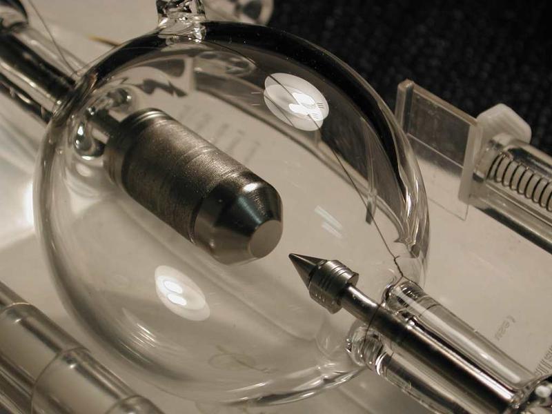
A xenon arc lamp generates light by producing a high-temperature plasma of ionized xenon between two electrodes. It produces bright white light that has a spectrum similar to daylight and is useful for movie projectors, searchlights, and laboratory uses. Although the lamp is powered by a low-voltage, high-current DC power supply, a high-voltage spark is required to start the arc, and that is the role of this 40 kV igniter.
I searched for information on this ignitor. The only thing I found was a 1964 paper titled A Spectrofluorophosphorimeter that described an experimental setup for measuring fluorescence and phosphorescence spectra. The experiment used a 450-W Osram xenon arc lamp, ignited by a Z2201 igniter, the same as this one. The research was done at SRI (Stanford Research Institute), just a few miles away, so there's a good chance that Marc obtained the exact unit that was used in this research.
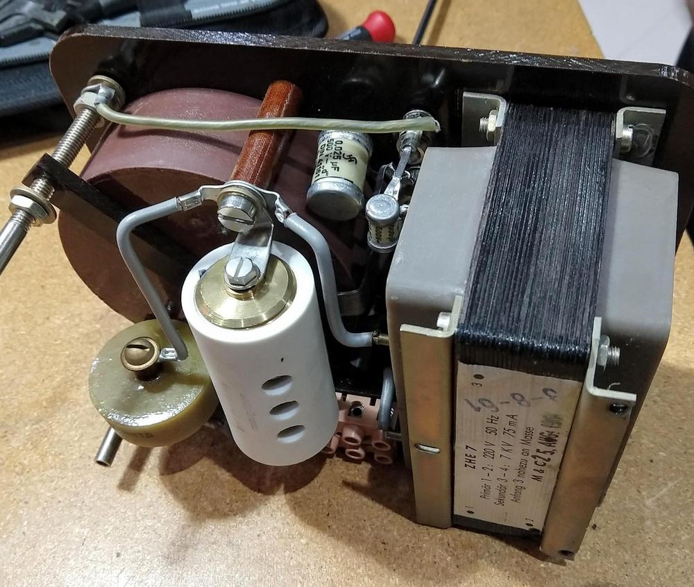
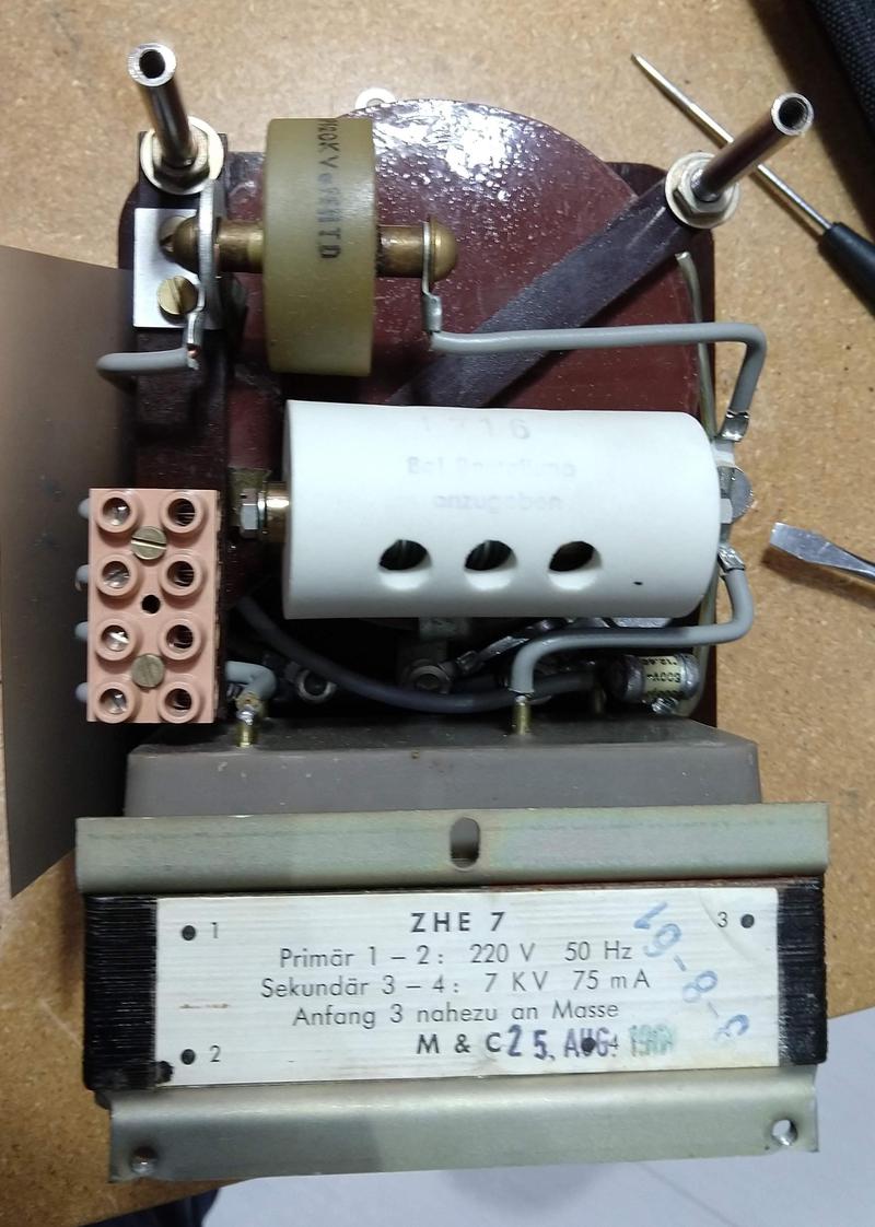
We opened up the unit and I examined the unusual components inside. A large 220V to 7kV transformer is at the right of the photo below. The output transformer is the reddish flat cylinder at the back left; this transformer's output is the connection pillar on the front of the unit. In front of this transformer is a dark yellowish disk, a 1000pF 20kV capacitor. The most unusual component is the ceramic cylinder in the front.
I traced out the circuitry of the unit6. It is a high-voltage circuit that is also sometimes used in Tesla coils (details). The way it works is that the high voltage transformer raises the 220 V input to 7 kV. This charges the high-voltage "tank" capacitor until it has enough voltage to break down the spark gap, causing a spark across it. When the spark gap fires it conducts at low resistance. This creates a high-frequency resonant circuit between the tank capacitor and the output transformer's primary. Energy is transferred to the secondary, at a much higher voltage, producing the 40 kV output. As energy shifts back and forth between the primary and secondary, it is dissipated, until the spark gap stops conducting and the process repeats, thousands of times a second.5
So where is the spark gap in this unit? It turns out to be the ceramic cylinder. I opened up the cylinder and found a stack of eight metal disks with (maybe) carbon electrodes in the center. The disks are separated by mica washers to leave 0.33 mm gaps between each pair. This forms a series of 7 tiny spark gaps.
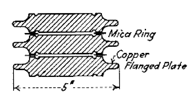
This type of spark gap is known as a "quenched spark gap". Spark gap transmitters were the first form of radio transmitter, used from 1887 to 1920. They used a spark to transmit Morse code via radio waves (details). The quenched spark gap was one type of spark gap used in these transmitters, as shown in the diagram below. By combining multiple small gaps, the quenched spark gap could cool off efficiently.
Repair
We cautiously hooked the igniter to 220V to test it, but nothing happened. I checked various parts of the circuit and everything seemed fine. In the photo below, notice the pink block at the left that looks like a Lego piece. This is a safety interlock that disconnects the 220 V input if the case is removed; the case has prongs that mesh with the interlock to close the circuit. Eventually, we figured out that the safety interlock had some loose screws that weren't making contact. This was tricky to find because when the case was open, the safety interlock was (of course) open.
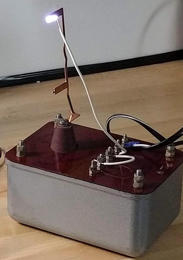
After tightening all the screws, the igniter worked. Since we didn't have a xenon arc lamp, we used the unit to generate sparks instead. Marc attached a strip of copper to the center output and a white wire to the ground, bending them to form a small gap. He pulsed the power switch to produce brief sparks, as seen in the video below. (Since the text on the unit indicates the unit should be powered for under 0.5 seconds, we kept the sparks brief to prevent overheating.) Although the repair was anticlimactic, at least we got some nice sparks.
Conclusion
Spark gaps generate radio waves across a wide spectrum;5 inventor David Hughes first noticed this interference in 1878. Marconi experimented with spark-gap transmitters in the 1890s, discovering how to transmit telegraph signals across short distances and then between continents. This work won Marconi the Nobel Prize for inventing radio. The CuriousMarc video below explains in more detail how the spark gap generator led to radio. Vacuum tubes made spark-gap transmitters obsolete by the 1920s, but these spark-gap circuits live on, igniting xenon arcs in modern headlights.
I announce my latest blog posts on Twitter, so follow me @kenshirriff for future articles. I also have an RSS feed.
Notes and references
-
You might know Osram as the maker of headlights4 and other lights. The story starts with the Austrian chemist Carl Auer von Welsbach, who discovered four elements as well as inventing the gas mantle (used in Coleman lamps) and the metal flint used in lighters. He registered Osram as a trademark in 1906; the name was a combination of osmium and wolfram (tungsten), two elements he used in incandescent lamp filaments. In 1919, the Osram company was formed in Germany. ↩
-
The document Osram guidelines for control gear and igniters discusses the properties of xenon arc lamps, how to power them, and the characteristics of igniters. ↩
-
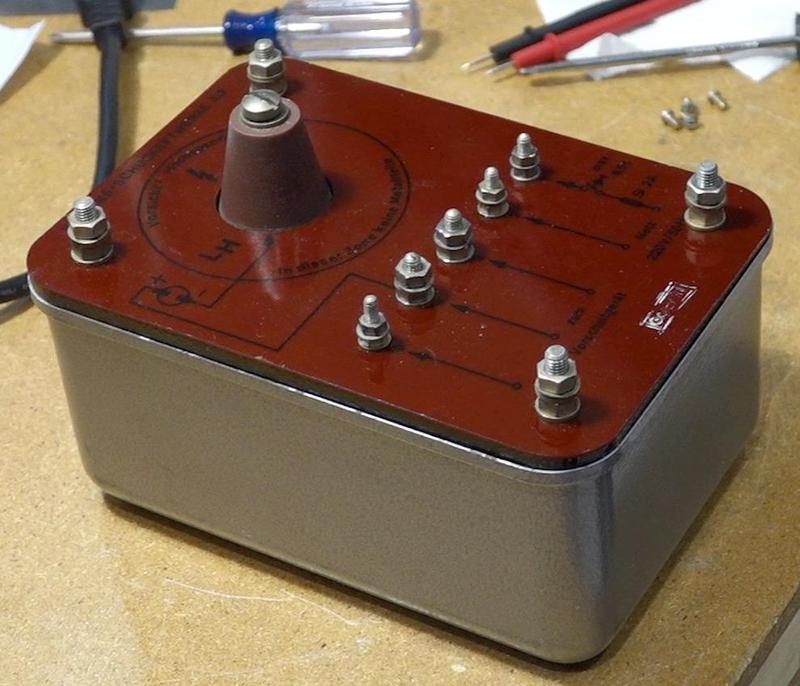
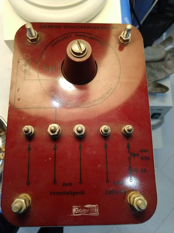
The front of the unit is shown below. Siemens-Schuckertweke AG is a German engineering company that I think owned Osram at the time. Under that are the warnings "Vorsicht! Hochspannung" (Danger! High voltage) and a circle labeled "In diesen Zone keine Metallteile" (No metal parts in this zone). At the center of the circled zone is a pillar with a screw terminal; this is the connection for the 40 kV output. At the bottom are connections for 220V / 50 Hz, which can be applied for a maximum of 0.5 s, as well as "zum Vorschaltgerät" (to the ballast).
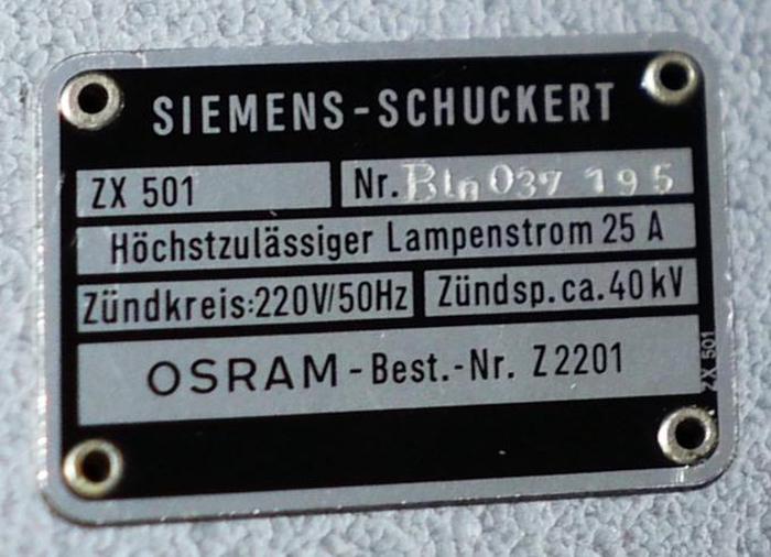
Front view of the igniter. The black text is hard to read under the brown front.The label on the back of the unit (below) says ZX 501, Höchstzulässiger Lampenstrom 25 A (Maximum lamp current 25 A), Zündkreis (Ignition circuit) 220V/50Hz, Zündsp. ca. 40 kV (Ignition voltage approximately 40 kV), OSRAM - Best. - Nr. (Order number) Z2201. "
The label on the back of the unit. Photo courtesy of Marc Verdiell. -
Xenon headlights are also known as HID (high-intensity discharge) headlights. These headlights produce most of their light from an arc through vaporized metal halides, such as scandium iodide. However, it takes seconds to minutes for the light to heat up enough to vaporize these halides. During this startup time, a xenon arc provides the headlight's illumination. In other words, the xenon arc is just to provide light temporarily until the metal halides kick in. HID headlights require an igniter/ballast circuit to provide the high voltage (25 kV) for ignition and the regulated voltage (e.g. .41A, 85V) to power the light. These automotive circuits use modern switching power supply techniques and are much smaller than our igniter. ↩
-
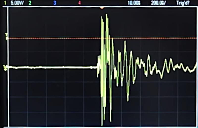
We measured the output from the igniter and found that it produces 2000-4000 very short spikes a second. The spikes decay very rapidly so they are about 1µs long, and are random noise in the tens of megahertz. This random noise has a very wide bandwidth showing that spark gap generators produce radio noise across a wide spectrum.
Oscilloscope trace pickingup electrical noise from the igniter over the air. Image from CuriousMarc's video. -
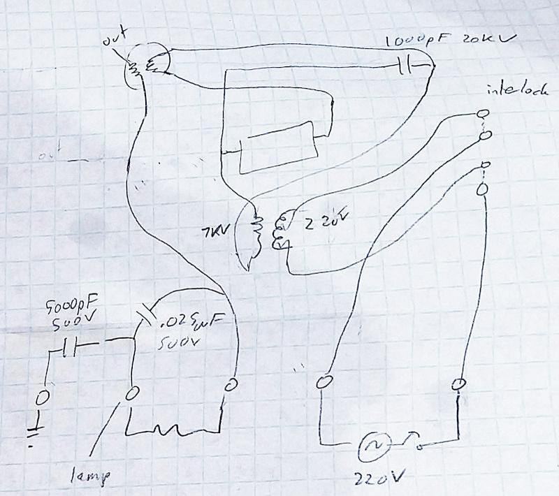
I traced out the circuitry of the unit and made the rough schematic below. The unlabeled rectangle is the ceramic spark gap cylinder. The circuit is essentially the same as the Tesla coil schematic earlier, except there are two capacitors and an external ballast resistor on the output side to limit current. (We did not use a ballast resistor, but shorted the two connections.)
Schematic of the spark generator.


7 comments:
Amazing! Thank you.
You guys have the best fun!!
Might want to check the text of the ''inside the igniter' photo caption..
I think the last sentence should be referring to the OTHER transformer.
Anonymous: thanks for the correction; I've fixed the caption.
Some subtleties in the translations:
Vorsicht: caution, watch out, beware, not necessarily "danger" (which would translate back as "Gefahr")
Höchstzulässiger ... = maximum allowed
In dieser Zone (as labeled)
Larger versions of these igniters, often made by an Italian company IREM, are used in the lamphouses of cinema film projectors in order to strike the xenon lamp. Typically the lamp is rated from 1kw upwards. I came across your page when recently repairing just such an igniter that had stopped striking. They are not cheap units to replace, so I was happy to find that the fault lay with the spark generator.
Thanks for your useful explanation of the circuitry, which helped me out here.
cheers! Phil
I wish this video never end.
Post a Comment