The Nanoprocessor is a mostly-forgotten processor developed by Hewlett-Packard in 19741 as a microcontroller2 for their products. Strangely, this processor couldn't even add or subtract,3 probably why it was called a nanoprocessor and not a microprocessor. Despite this limitation, the Nanoprocessor powered numerous Hewlett-Packard devices ranging from interface boards and voltmeters to spectrum analyzers and data capture terminals.4 The Nanoprocessor's key feature was its low cost and high speed: Compared against the contemporary Motorola 6800,7 the Nanoprocessor cost $15 instead of $360 and was an order of magnitude faster for control tasks.
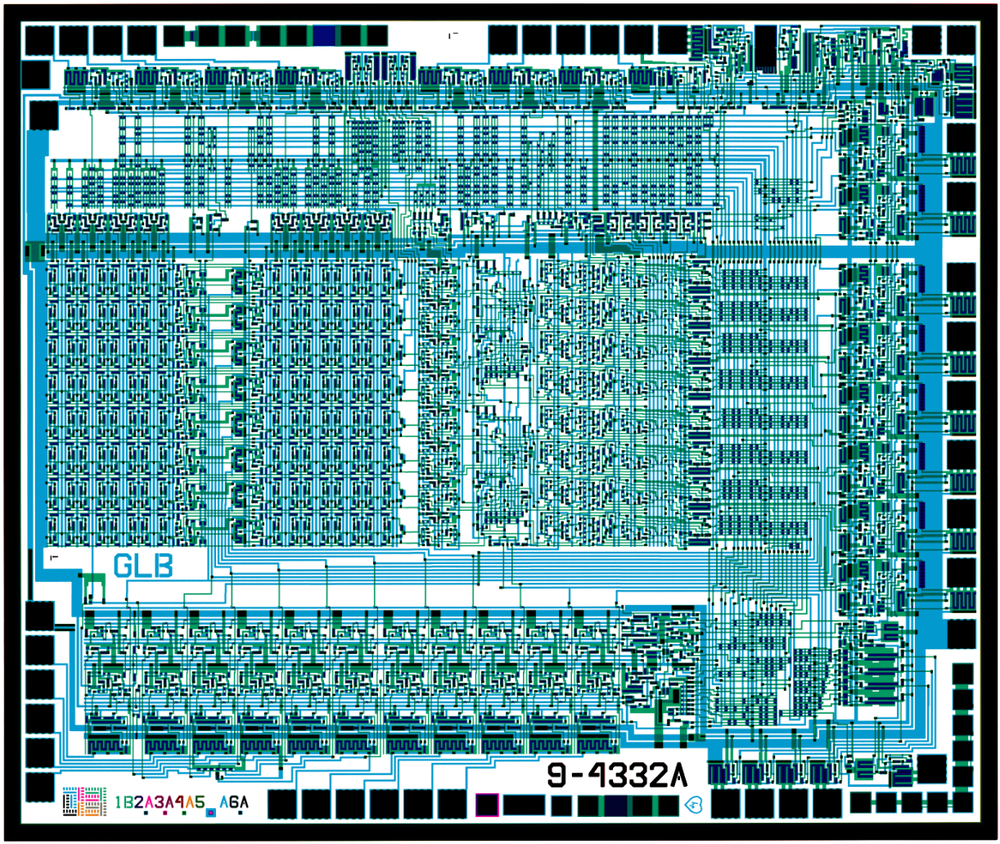
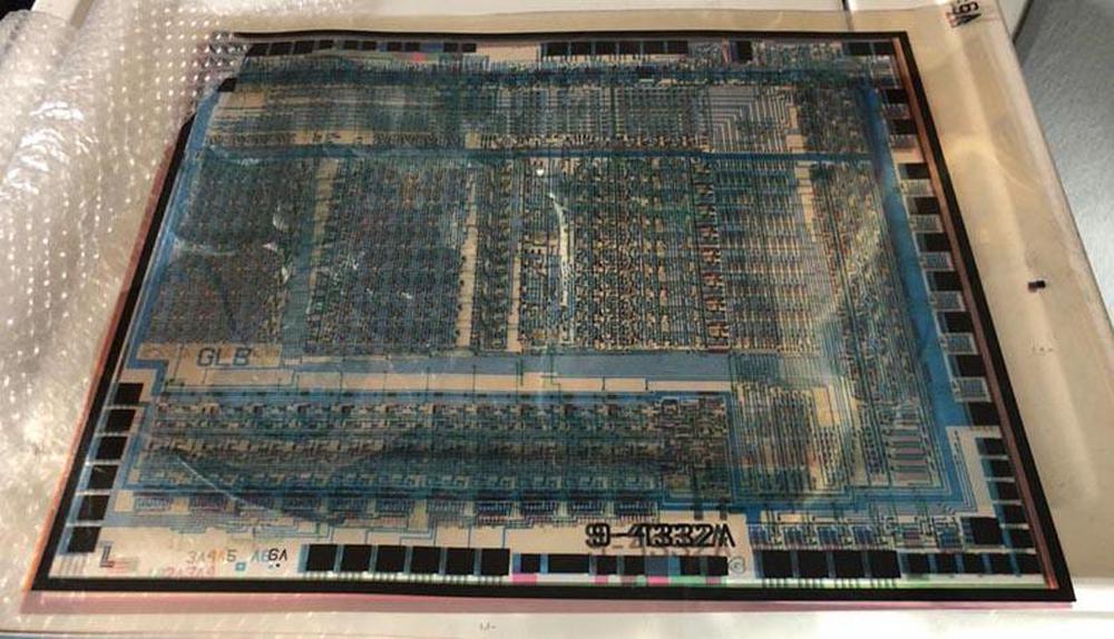
Recently, the six masks used to manufacture the Nanoprocessor were released by Larry Bower, the chip's designer, revealing details about its design. The masks were carefully cleaned and scanned by The CPU Shack, and stitched by Antoine Bercovici. The composite mask image below shows the internal circuitry of the integrated circuit.5 The blue layer shows the metal on top of the chip, while the green shows the silicon underneath. The black squares around the outside are the 40 pads for connection to the IC's external pins. I used these masks to reverse-engineer the circuitry of the processor and understand its simple but clever RISC-like design.6
The Nanoprocessor was designed in 1974, the same year that the classic Intel 8080 and Motorola 6800 microprocessors were announced. However, the Nanoprocessor's silicon fabrication technology was a few years behind, using metal-gate transistors rather than silicon-gate transistors that were developed in the late 1960s. This may seem like an obscure difference, but silicon gate technology was much better in several ways. First, silicon-gate transistors were smaller, faster, and more reliable. Second, silicon-gate chips had a layer of polysilicon wiring in addition to the metal wiring; this made chip layouts about twice as dense.8 Third, metal-gate circuitry required an additional +12 V power supply. The Intel 4004 processor used silicon gates in 1971, so I'm surprised that HP was still using metal gates in 1974.9
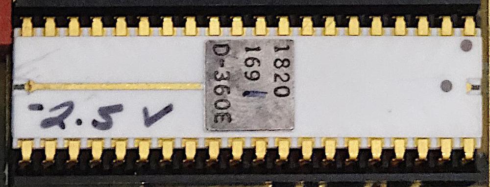
A bizarre characteristic of the Nanoprocessor is its variable substrate bias voltage. For performance reasons, many 1970s microprocessors applied a negative voltage to the silicon substrate, with -5V provided through a bias pin.10 The Nanoprocessor has a bias pin, but strangely the bias voltage varied from chip to chip, from -2 volts to -5 volts. During manufacturing, the required voltage was hand-written on the chip (below). Each Nanoprocessor had to be installed with a matching resistor to provide the right voltage. If a Nanoprocessor was replaced on a board, the resistor had to be replaced as well. The variable bias voltage seems like a flaw in the manufacturing process; I can't imagine Intel making a processor like that.
Like most processors of that era, the Nanoprocessor was an 8-bit processor. However, it didn't use RAM, but ran code from an external 2-kilobyte ROM. It contained 16 8-bit registers, more than most processors and enough to make up for the lack of RAM in many applications. Based on transistor count, the Nanoprocessor is more complex than the Intel 8008 (1972) and slightly less complex than the 6800 (1974) or 6502 (1975).11 Its architecture uses its transistor count on different purposes from these processors, though. The Nanoprocessor lacks ALU functionality but in exchange, it has a large register set, taking up much of the die area. The Nanoprocessor has 48 instructions, a considerably smaller instruction set than the 6800's 72 instructions. However, the Nanoprocessor includes convenient bit set, clear, and test operations, which these other processors lacked.12 The Nanoprocessor supports indexed register access, but lacks the complex addressing modes of the other processors.
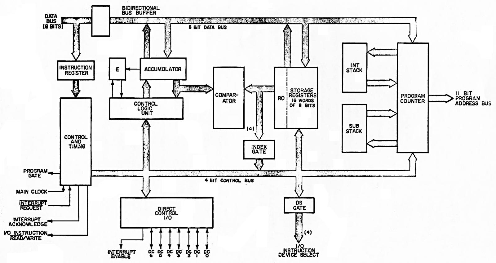
The block diagram below shows the internal structure of the Nanoprocessor. The main I/O feature is the 4-bit "I/O Instruction Device Select" which allows 15 devices to receive I/O operations. In other words, the select pins indicate which I/O device is being read or written over the data lines. External circuitry uses these signals to do whatever is necessary for the particular application, such as storing the data in a latch, sending it to another system, or reading values. More I/O is provided through seven "Direct Control I/O" pins (GPIO pins) that can be used for inputs or outputs. If not connected to external circuitry, these pins operate as convenient bit flags; the Nanocomputer can set a value and then read it back. The Control Logic Unit performs increments, decrements, shifts, and bit operations on the accumulator, lacking the arithmetic and logical operations of a standard Arithmetic/Logic Unit (ALU).
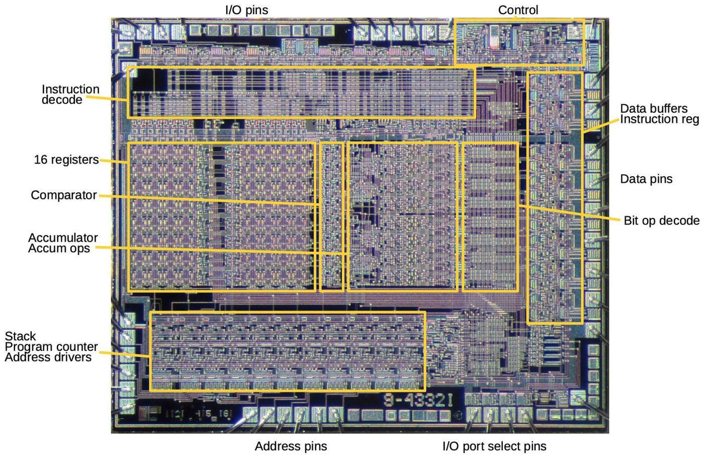
I reverse-engineered the Nanoprocessor's circuitry from the masks and determined how the functional blocks map onto the die, below. The largest feature is the set of 16 registers in the center-left. To the right is the comparator and then the accumulator, along with its increment, decrement, shift, and complement circuitry. The instruction decoder circuitry takes up much of the space above and to the right of the comparator and accumulator. The bottom part of the chip is dominated by the 11-bit program counter, along with the one-entry interrupt stack and subroutine stack. The control circuitry implements the Nanoprocessor's almost-trivial instruction timing: one fetch cycle followed by one execute cycle.13 In most microprocessors, the control circuitry takes up a large fraction of the chip, but the Nanoprocessor's control circuitry is just a small block.
Understanding the masks
The chip was fabricated using six masks, each used for constructing one layer of the processor using photolithography. The photo below shows the masks; each one is a 47.2×39.8 cm Mylar sheet. These sheets are 100× enlargements of the masks used to produce the 4.72×3.98 mm silicon die (for comparison, about 33% smaller than the 6800's die). Each 3-inch silicon wafer held about 200 integrated circuits, fabricated together on the wafer, and then tested, cut apart, and packaged.
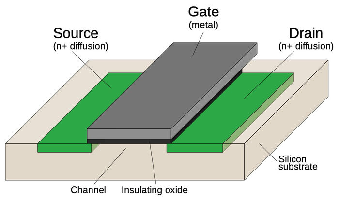
To explain the role of the masks, I'll start with the structure of a metal-gate MOSFET, the transistor used in the Nanoprocessor. At the bottom, two regions of silicon (green) are doped to make them conductive, forming the source and drain of the transistor. A metal strip in between forms the gate, separated from the silicon by a thin layer of insulating oxide. (These layers—Metal, Oxide, Semiconductor—give the MOS transistor its name.) The transistor can be considered a switch controlled by the gate. The metal layer also provides the main wiring of the integrated circuit, although the silicon layer is also used for some wiring.
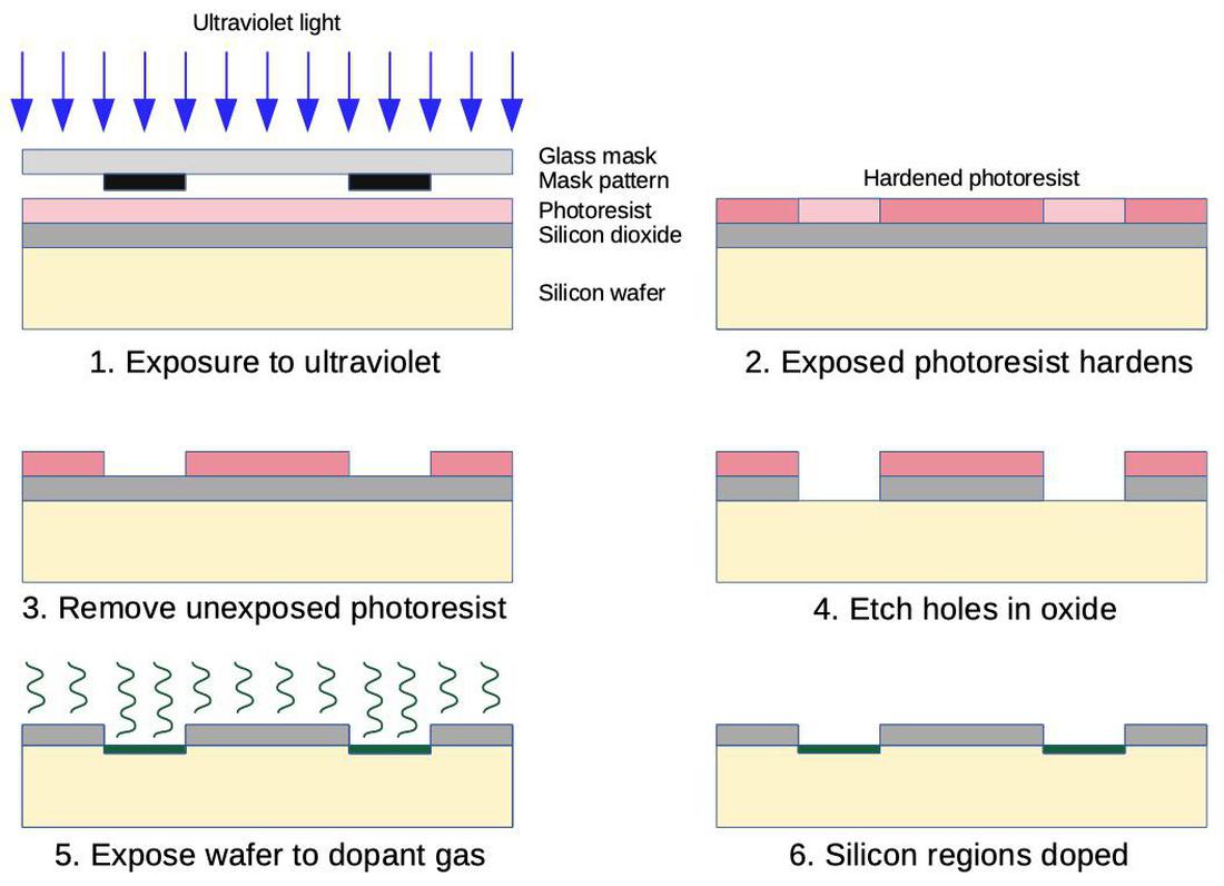
Masks are a key part of the integrated circuit construction process, specifying the position of the components. The diagram below shows how a mask is used to dope regions of the silicon. First, the silicon wafer is oxidized to form an insulating oxide layer on top, and then light-sensitive photoresist is applied. Ultraviolet light polymerizes and hardens the photoresist, except where the mask blocks the light. Next, the soft, unexposed photoresist is dissolved. The wafer is exposed to hydrofluoric acid, which removes the oxide layer where it is not protected by photoresist. This yields holes in the oxide that match the mask pattern. The wafer is then exposed to a high-temperature gas which diffuses into the unprotected silicon regions, modifying the silicon's conductivity. These processing steps create tiny doped silicon regions matching the masks's pattern. As will be shown below, the other masks are used for different processing steps, but using the same photoresist-and-mask process.
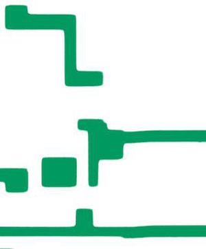
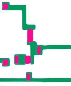
I'll zoom in on the Nanoprocessor's die and show how one of its circuits is constructed from the six masks. (This two-transistor circuit is an inverter, flipping the binary value of its input.) The first mask dopes regions of silicon to make them conductive, using the photolithography steps described above. The doped regions (green) will become transistor source/drains or wiring between components.
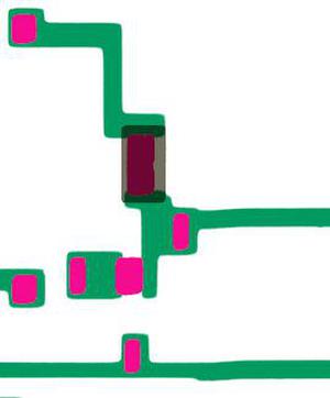
Next, the die is covered with an insulating oxide layer. The second mask (magenta) is used to etch openings in the oxide, exposing the silicon underneath. These openings will be used to create transistor gates as well as connecting metal wiring to the silicon.
The third mask (gray) exposes a region to ion implantation, which changes the doping of the silicon, and thus the transistor's properties. This turns the upper transistor into a special depletion-mode transistor that pulls logic gate outputs high.
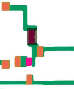
Next, the silicon is covered with an additional thin layer of insulating oxide, forming the gate oxide for the transistors. The fourth mask (orange) removes this oxide from regions that will become contacts between the silicon and the metal layer. After this step, most of the die is covered with a thick insulating oxide layer. The oxide layer is very thin over the transistor gates (magenta), and there are contact holes in the oxide from the current mask (orange).
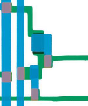
The fifth mask (blue) is used to create the metal wiring on top; a uniform metal layer is applied and then the undesired parts are etched off. In locations where the fourth mask created holes in the oxide, the metal layer contacts the silicon and forms a connection. In locations where the third mask created a thin oxide layer, the metal layer forms the transistor gate between two silicon regions. Finally, the entire wafer is covered with a protective glassy layer. The sixth mask (not shown) is used to form holes in this layer over the pads around the edges of each chip. Once the wafer is cut into individual silicon dies (dice?), bond wires are attached to the pads, connecting the die to the external pins.
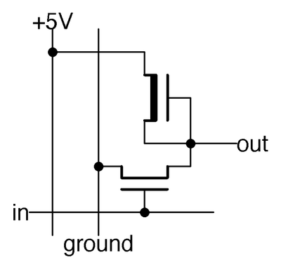
The schematic below shows how the circuitry above forms a two-transistor inverter. The two transistor symbols correspond to the two transistors created by the masks. When there is no input, the upper transistor (connected to +5 volts) pulls the output high. When the input is high, it turns on the lower transistor. This connects the output to ground, pulling the output low. Thus, the circuit inverts the output.
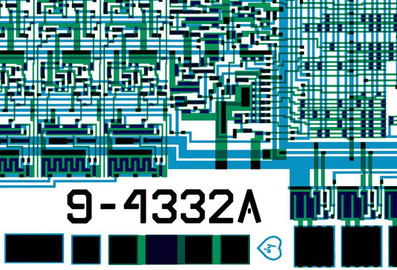
Although the diagrams above show just a single inverter, these masking steps create the entire processor with its 4639 transistors.11 The diagram below shows a larger part of the die with dozens of transistors forming more complex gates and circuitry. One cute thing I noticed on the masks is a tiny heart with HP inside, below the chip's number.14
Controlling a clock with the Nanoprocessor
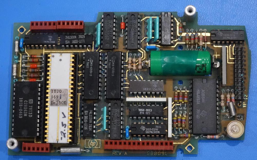
To understand how the Nanoprocessor was used in practice, I reverse-engineered the code from an HP 98035 clock module. This module was plugged into an HP desktop computer15 to provide a real-time clock, as well as millisecond-accurate timings, intervals, and periodic events. The design of the clock module was rather unusual. To preserve the time when the computer was powered-down, the clock module was built around a digital watch chip with a backup battery.17 Inconveniently, the digital watch chip wasn't designed for computer control: it generated 7-segment signals to drive an LED, and it was set through three buttons. To read the time, the Nanoprocessor had to convert the 7-segment display outputs back into digits. And to set the time, the Nanoprocessor had to simulate the right sequence of button presses to advance through the digits.
The host computer controlled the clock module by sending it ASCII strings such as "S 12:07:12:45:00" to set the clock to 12:45:00 on December 7 (or on July 12 if the module was running in European mode). The module's various interval timers, periodic alarms, and counters were controlled with similar commands such as "Unit 2 Period 12345". The module supported 24 different commands, and the Nanoprocessor had to parse them. (See the manual for details.)
Here's some sample code reverse-engineered from the clock board ROM. This code is from the interrupt handler that increases the time and date every second. The code below determines how many days in the current month so it knows when to move to the next month. The columns are the byte value, the corresponding opcode, and my description of the instruction.
This code takes a month number (01-12 BCD) in the accumulator and returns (in register 0) the number of days in the month (28, 30, or 31 BCD). Not bad for 16 bytes of code, even if it ignores leap years. How does it work? For months past 7 (July), it subtracts 1. Then, if the month is odd, it has 31 days, while an even month has 30 days. To handle February, the code clears bit 1 of the month. If the month is now 0 (i.e. February), it has 28 days.
This code demonstrates that even though a processor without addition sounds useless, the Nanoprocessor's bit operations and increment/decrement allow more computation than you'd expect.16 It also shows that Nanoprocessor code is compact and efficient. Many things can be done in a single byte (such as bit test and skip) that would take multiple bytes on other processors.12 The Nanoprocessor's large register file also avoids much of the tedious shuffling of data back and forth often required in other processors. Although some call the Nanoprocessor more of a state machine controller than a microprocessor, that understates the capabilities and role of the Nanoprocessor.
While the Nanoprocessor doesn't include an ALU or have instructions for accessing RAM, these could be added as I/O devices. The clock module has 256 bytes of RAM to hold its multiple counter and timer values, accessed through four I/O ports. Other products added ALU chips to support arithmetic operations.18
Conclusions
The Nanoprocessor is an unusual processor. My first impression was that it wasn't even a "real processor", lacking basic arithmetic functionality. The chip was built with obsolete metal-gate technology, a few years behind other microprocessors. Most bizarrely, each chip required a different voltage, hand-written on the package, suggesting difficulty with manufacturing consistency. However, the Nanoprocessor provided high performance in its microcontroller role, much faster than other processors at the time. Hewlett-Packard used the Nanoprocessor in many products in the 1970s and 1980s, in roles that were more complex than you'd expect. strings and performing calculations.
While the Nanoprocessor has languished in obscurity, without even a mention on Wikipedia, the masks recently revealed by its designer shed light on this unusual corner of processor history. Thanks to Larry Bower for the donation of the masks, John Culver at The CPU Shack for scanning and sharing the masks, and Antoine Bercovici for remastering the masks. Thanks to Marc Verdiell for dumping the clock board ROM.
I plan to write about the internal circuitry of the Nanoprocessor so follow me on Twitter at @kenshirriff for updates on Part II. I also have an RSS feed.
Notes and references
-
More information on the HP Nanoprocessor and its history is in CPU Shack's recent article The Forgotten Ones: HP Nanoprocessor, as well as at HP9825.com and The HP 9845 Project. ↩
-
I'm not completely comfortable calling the Nanoprocessor a microcontroller since it uses an external program ROM, while a microcontroller usually has everything, including the ROM, on a single chip. (It is like the Intel 4004 in this way.) However, the Nanoprocessor resembles a microcontroller in most ways: it is designed for embedded control applications, with a Harvard architecture and an instruction set optimized for I/O, running a program from ROM with minimal storage. ↩
-
On the topic of computers that can't add, the desk-sized IBM 1620 computer (1959) didn't have addition circuitry, but used table lookup for addition. It had the codename CADET; people joked that this stood for "Can't Add, Doesn't Even Try." ↩
-
I've determined that the Nanoprocessor was used in the following HP products (and probably others): HP 9845B, HP 3585A spectrum analyzer, HP 3325A Synthesizer / Function Generator, HP 9885 floppy disk drive, HP 3070B data capture terminal, HP 98034 HPIB interface for the HP 9825 calculator, HP 98035 real time clock for the HP 9825 desktop computer, HP 7970E tape drive interface, HP 4262A LCR meter, HP 3852 Spectrum Analyzer, and HP 3455A voltmeter. Poul-Henning Kamp informs me that the HP 3336 Synthesizer / Function Generator and HP 9411 Switch Controller also used the Nanoprocessor. I've also been informed that the HP3437A System Voltmeter uses the Nanoprocessor. ↩
-
The mask images can be downloaded here (warning: 122 MB PSD file). ↩
-
The Nanoprocessor is like a RISC (Reduced Instruction Set Computer) processor in many ways, although it predated the RISC concept by several years. In particular, the Nanoprocessor is designed with a simple opcode structure, all instructions execute in one cycle (after the fetch cycle), the register set is large and orthogonal, and addressing is simple. These RISC characteristics yielded a high clock speed compared to more complex processors. ↩
-
Interestingly, the Nanoprocessor's competition during development was the Motorola 6800, rather than an Intel processor. The Nanoprocessor's key feature was performance: it ran at 4 MHz, compared to 1 MHz for the 6800. (Both processors took 2 cycles to perform a basic instruction, while the 6800 took up to 7 cycles for more complex instructions.)
The Nanoprocessor designers wrote a timing comparison, estimating that the Nanoprocessor could count six times faster than the 6800 and handle interrupts over sixteen times faster. The proposal assumed a 5 MHz Nanoprocessor while the actual chip fell a bit short, running at 4 MHz. The projected cost of the Nanoprocessor was $15 per chip, compared to $360 for the Motorola 6800. ↩
-
I'm impressed with the density of the Nanocomputer's layout given its limitations: one layer of metal wiring and no polysilicon. I've looked at other metal-gate chips and their layouts are horribly inefficient, with a lot more wiring than transistors. However, the Nanoprocessor's circuits are arranged efficiently, with very little wasted space. ↩
-
The Nanoprocessor's fabrication technology was ahead of the Intel 8080 and Motorola 6800 in one way: it used depletion-mode pull-up transistors, more advanced than the enhancement-mode transistors in the 8080 and 6800. Depletion-mode transistors resulted in faster, lower-power logic gates, but required an additional manufacturing step. For the Nanoprocessor, this step used mask #3 (the gray mask). In processors such as the MOS Technology 6502 and Zilog Z-80, depletion-mode transistors allowed the processor to run off a single voltage instead of three. Unfortunately, the Nanoprocessor still required three voltages due to its metal-gate transistors. ↩
-
Early DRAM memory chips and microprocessor chips often required three supplies: +5V (Vcc), +12V (Vdd) and -5V (Vbb) bias voltage. In the late 1970s, improvements in chip technology allowed a single supply to be used instead. The Intel 8080 microprocessor (1974) used enhancement-mode transistors and required three voltages, but the improved 8085 (1976) used depletion-mode transistors and was powered by a single +5V supply. Starting in the late 1970s, many microprocessors used an on-chip charge pump to generate the negative bias voltage. I wrote about the 8086's charge pump here. ↩
-
By my count, the Nanoprocessor has 4639 transistors. The instruction decoder is constructed from pairs of small transistors for layout reasons; combining these pairs yields 3829 unique transistors. Of these, 1061 act as pull-ups, while 2668 are active. In comparison, the 6502 has 4237 transistors, of which 3218 are active. The 8008 has 3500 transistors and the Motorola 6800 has 4100 transistors. ↩↩
-
Early microprocessors didn't have bit set, reset, and test operations (although these could be accomplished with AND and OR). The Z-80 (1976) added bit operations, but they took two bytes and were much slower than the Nanoprocessor. ↩↩
-
The Nanoprocessor sticks to its model of executing the instruction in one cycle even for two-byte instructions: The second byte is fetched during the execute cycle, so the overall timing is unchanged. ↩
-
The Nanoprocessor has two different part numbers. The 1820-1691 was the 2.66 MHz version, while the 1820-1692 was the 4 MHz version. The last digit of the part number was hand-written on each chip after testing its performance. (The part number is unrelated to the chip's number 9-4332A on the die.) ↩
-
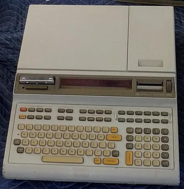
The HP 9825 was a 16-bit desktop computer, running a BASIC-like language. It was introduced in 1976, five years before the IBM PC, and was a remarkably advanced system for its time. The back of the HP 9825 had three I/O slots for adding modules such as the real time clock.
An HP 9825 with tape drive, LED display, and printer. From Marc Verdiell's collection. -
I came across one place in the code where it needs to add two BCD digits to form one byte. This was accomplished by a loop that decremented one number while incrementing the second. When the first number reached zero, the result was the sum. Thus, even without an ALU, addition is possible but slow. ↩
-
The Texas Instruments watch chip was implemented with Integrated Injection Logic (I2L) to keep power consumption low. Nowadays, a low-power chip would use CMOS, but that wasn't common at the time. Integrated Injection Logic was built from bipolar transistors, similar to TTL, but using different high-density, low-power circuitry. I discussed Integrated Injection Logic in detail in this blog post. The Texas Instruments chip may be the X-902 in a DIP package. ↩
-
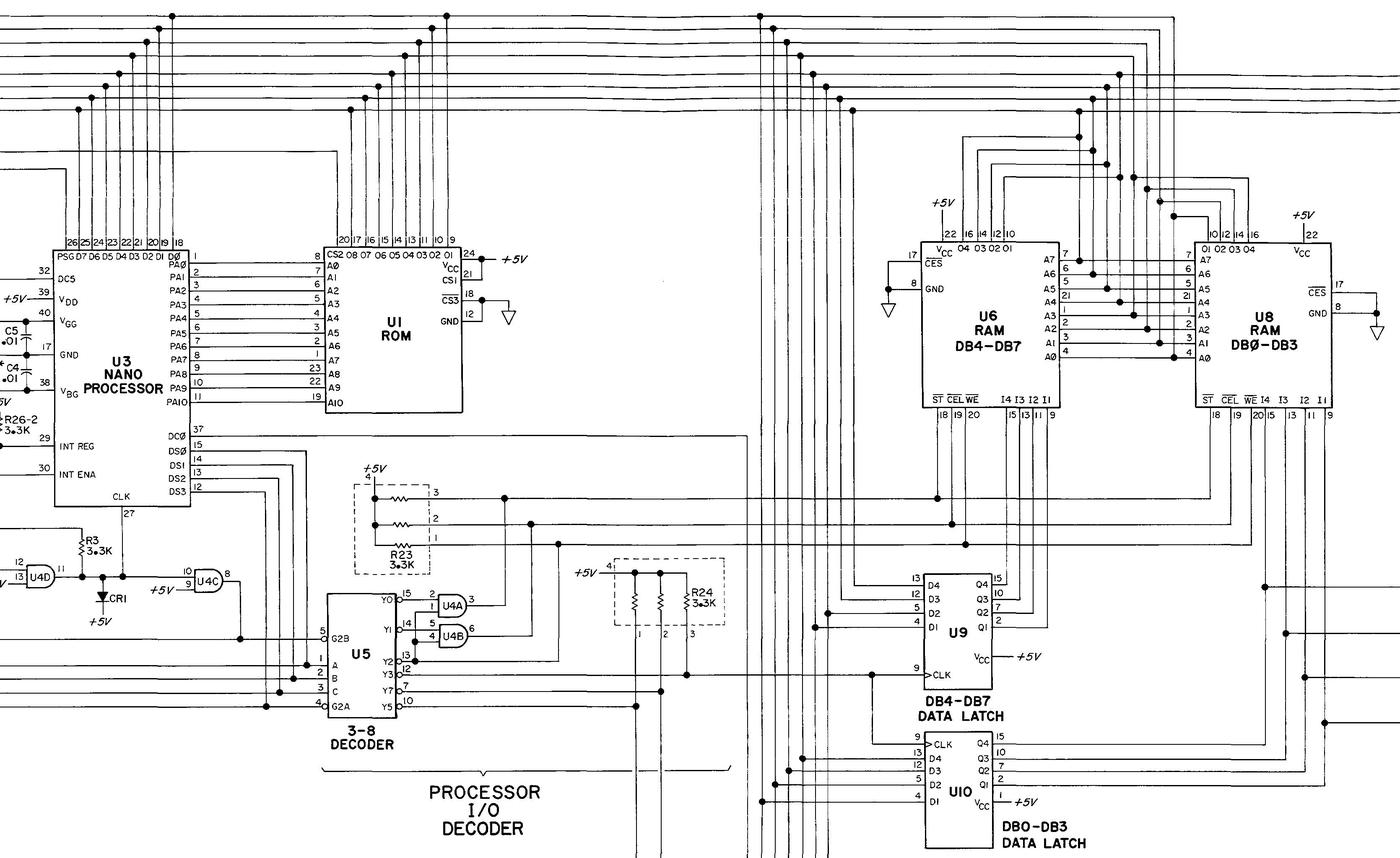
The clock board schematic shows how the two 256×4 RAM chips are connected to the Nanoprocessor. The Nanoprocessor's I/O port select pins are connected to the "3-8 Decoder" U5, which produces a separate signal for each I/O port. Three of these signals go to the RAM chip's control pins, while one signal controls the Data Latch chips U9 and U10 that hold write data.
RAM chips connected to the Nanoprocessor. From the Clock service manual.All I/O ports use the Nanoprocessor's data bus (top) for communication, so the data bus is connected to both the address and data pins of the RAM chips. For a read, the RAM address is written to the RAM chips via one I/O port and then the data is read from RAM via a second port. In both cases, the values go across the data bus, while the signal from the "3-8 Decoder" indicates what to do with the values. For a write, the first I/O operation stores the byte value in the latches, and then the second I/O operation sends the address to the RAM chips. While this may seem like a clunky, Rube-Goldberg approach, it works well in practice; a read or write can be done with two bytes of instructions.
(Many processors, such as the 6502, used memory-mapped I/O; I/O devices were mapped into the memory address space and accessed through memory read/write operations. The Nanoprocessor is the opposite, putting RAM into the I/O port space and accessing it through I/O operations.)
Adding an ALU uses a similar approach, as in the HP 3455A voltmeter (schematic), which contains two Nanoprocessors. The voltmeter uses two 74LS181 ALU chips to implement an 8-bit ALU that it uses to scale value and compute percentage error. Two output ports provide the arguments and another port specifies the operation. The 8-bit result is read from a port, while the processor reads the carry through a GPIO pin. (At this point, I'd wonder if it wouldn't be better to use a processor that includes arithmetic.) ↩
17 comments:
Footnote #15: When putting the 9825 (of 1976) into context it may be more relevant to use it's contemporary competition, like the Olivetti 6060 and the IBM 5100, both of 1975. It's said that the P6060 made much impression at HP.
I used a hp nanoprocessor to make a gas chromatograph in 1974 or 5. I made an addroutine that started at the msb and to implement carry i used the “increment” instruction.. left shifting until lsb.
I found the discussion about the manufacturing process very interesting as well. Are today's modern processors built using masks and photoresist chemicals as well? If so, I'm surprised that isn't more of a limiting factor than just the wavelength of the light.
Also, I found the doping technique to be interesting, and it made me think that the cross-section diagrams are a little misleading with the hard angular edges and the homogeneous region of doped silicon. I'd expect this process to create more blob like areas of doping and for the concentration of dope atoms to gradually decrease, not stop suddenly.
Apropos Injinear's comment on an addition algorithm, and the articles mention of just counting the increments to achieve addition, a fun exercise would be to try to come up with the most clever and efficient algorithms for addition and even multiplication or division on these nanoprocessors.
Excellent post, as always.
In case you're interested I wrote a MAME emulation of nanoprocessor for 98034 (hpib) & 98035 (rtc) modules some time back. You can use the MAME debugger to see the RTC firmware in action. It's usually very instructive to see it run and be able to inspect/modify CPU & RAM state.
You mentioned the model of the TI watch chip: do you happen to know if there's any kind of doc/user manual around, please? I never found anything at all.
Also, the "hp inside heart" logo shows that the chip was designed in Loveland, CO. The hp9825.com site mentions it IIRC.
Perhaps the metal-gate process was chosen to make use of older fab equipment that was idled and otherwise obsolete.
How cool. I was just fixing a 3325A and it was interesting to see the handwritten bias voltage on the processor. Excellent article Ken, as always.
who needs an alu? counter machines are turning complete.
Very interesting!
Now I understand why the instruction manual of my 98035 RTC modules says setting the time might take up to 90 seconds... Simulating adjustment button key press... Who would have thought!
Absolutely fascinating.
As I did my electronics training in the 70's, this made absolute sense to me. What a handy little chip
Re: your Note 4. "I've determined that the Nanoprocessor was used in the following HP products (and probably others):"
Yes, the Nanoprocessor was also used in the HP 8568A spectrum analyzer, which shipped for a year or two before being superseded by the HP 8568B, which replaced the Nanoprocessor with a large ceramic 7-MHz 68000 with 128KB of ROM and 32KB of battery-backed SRAM.
More info here: http://www.hp9825.com/html/hybrid_microprocessor.html
Very nice article about a very obscure processor, Ken. I'm the author of the HP9825.com site and had a minor hands-on experience with the Nanoprocessor in the HP 98034A HPIB card for the HP 9825. In those days, HP was heavily invested in Tom Osborne's ASM (Algorithmic State Machine) design and I believe the Nanoprocessor was developed as a 1-chip (two chips if you include the ROM) ASM controller. Saying that the process technology used for the Nanoprocessor was behind that of Motorola and Intel at that time may be technically correct, but the fact that the Nanoprocessor had 4x the clock rate of early 8-bit chips explains why HP went the way it did. You are spot on when you point out that the variable back bias suggests that HP didn't have much process control back then, but on the other hand, the back bias was being used to juice the clock rate on the chips that could achieve it. Let's just say it was a way of squeezing out every last drop of performance from the available silicon.
my dad used an IBM 1620 when he was at the engineering school (in the late 60's).
a classic joke at the time was to replace the lookup tables with altered one so that the machine would do wonky arithmetic (say, 2+2 -> 5)
picture the other student scratching their heads at the wonky results...
Hi, I am currently repairing an HP 3437A system volmeter and it is also powered by a nanoprocessor, see https://twitter.com/douardda/status/1368994280581312513?s=20
David
Thanks for sharing this info!
Hi.
Interesting article, thanks.
I have an old HP3438A digital multimeter, that too uses one of the Nanoprocessors. even handling HPIB traffic!
The thing even works mostly to specification, except the HPIB hangs up. Not fully diagnosed it yet, but I suspect one of the bus handshake line drivers (part of U707 on the A3 board a 7438 is damaged. Hopefully, not the processors output pin that controls it.
73.
Dave G8KBV
Just a little proofreading for the Conclusion-part:
In the beginning of the last sentence there are one or more words missing.
Interesting. Maybe something like this (maybe even in a serial version) could be useful in some FPGA designs which need a little CPU support. Hmmmm..
Wikipedia has the User's guide.
Many thanks for a fine blog !
Post a Comment