A few days ago, I wrote about how I'm helping restore a Xerox Alto for Y Combinator. This new post describes the first day of restoration: how we disassembled the computer and disk drive and fixed a power supply problem, but ran into a showstopper problem with the disk interface.
The Xerox Alto was a revolutionary computer from 1973, designed by computer pioneer Chuck Thacker at Xerox PARC to investigate ideas for personal computing. The Alto was the first computer built around a mouse and GUI, as well as introducing Ethernet and laser printers to the world. The Alto famously inspired Steve Jobs, who used many of its ideas in the Lisa and Macintosh computer.
Alan Kay, whose vision for a personal computer guided the Alto, recently gave an Alto computer to Y Combinator. Getting this system running again is a big effort but fortunately I'm working with a strong team, largely from the IBM 1401 restoration team. Marc Verdiell, Luca Severini, Ron, Carl Claunch, and I started on restoration a few days ago, as shown in Marc's video below.
Disassembling the Alto
We started by disassembling the computer. The Xerox Alto has a metal cabinet about the size of a dorm mini-fridge, with a Diablo hard disk drive on top, and a chassis with power supplies and the circuit boards below. With some tugging, the chassis slides out of the cabinet on rails as you can see in the photo below. At the front are the four cooling fans, normally protected by a decorative panel. Note the unusual portrait layout of the display.

With the chassis fully removed, you can see the four switching power supplies on the left, the blue metal boxes. The computer's circuit boards are on the right, not visible in this picture. The wiring for the backplane is visible at right front, with pins connected by wire-wrapped wire connections. This wiring connects the circuit boards together.[1]
. On the right, the connections for the wire-wrapped backplane are visible. The circuit boards plug into this backplane.")
The power supplies
Our first goal was to make sure the power supplies worked after decades of sitting idle. The Alto uses high-efficiency switching power supplies.[2] To explain the power supplies in brief, input power is chopped up thousands of times a second to produce a regulated voltage. Unlike modern computer power supplies, there's a second switching stage (the inverter), which drops the voltage to the desired 15 volts. This was more complexity than I expected, but fortunately the detailed power supply manual was available online, thanks to Al Kossow's bitsavers.[3] We tested each power supply with a resistor as a dummy load and checked that the output voltage was correct. We also used an oscilloscope to make sure the output was stable. All the power supplies worked fine, except for the +15V supply (top center), which had trouble getting up to 15 volts and staying there.We disassembled the faulty power supply to track down the problem. The photo of the power supply below shows how densely components are crammed into the power supply. Two of the circuit boards have been removed and are at the back. Note the three large filter capacitors at the front.

We noted signs of overheating on the AC connector, as well as a somewhat sketchy looking repair (a trace replaced by a wire) and some signs of corrosion. Apparently the power supply had problems in the past and had been serviced. We cleaned up the corrosion and it appeared to be superficial.
The power supply disassembled easily for repair, as you can see below. The main board is at the right. The tower of three inductors on the main board is an unusual way of mounting inductors. Three circuit boards (top) plug into the main board. Because the power supply uses discrete components instead of a modern SMPS control IC, it needs a lot of control circuitry. The switching transistors (lower center) are mounted onto metal heat sinks for cooling.

The large capacitors were attached with screws, making it easy to remove them for testing. A capacitance meter showed that the three large capacitors had failed, explaining why the power supply had trouble outputting the desired voltage. Ron went off and found replacement capacitors, although they weren't an exact match for the originals. With the new capacitors mounted in place, the power supply worked properly.
Inside the Diablo disk drive
We also looked at the Diablo disk drive, which provides 2.5MB of storage for the Xerox Alto. The first step was removing the disk pack. In normal operation, the front of the drive is locked shut to keep the disk from being removed during use. To remove the disk without powering up the drive, we had to open the drive and manually trip the latch that locks it shut (see Diablo drive manual).This picture shows the disk pack being reinserted into the drive. Unlike modern hard disk drives, the Alto's disk can be removed from the drive. Users typically used different disks for different tasks — a programming disk, a word processing disk, and so forth. The disk pack is a fairly large white package, resembling a cross between an overgrown Frisbee and a poorly-detailed Star Wars spaceship. The drive's multiple circuit boards are also visible in the photo.[4]

As the disk pack enters the drive, it opens up to provide access to the disk surface. The photo below shows the exposed surface of the disk, brownish from the magnetizable iron oxide layer over the aluminum platter. The read/write head is visible above the disk's surface, with another head below the disk. The disk stores data in 203 concentric pairs of tracks, with the heads moving in and out together to access each pair of tracks.
 is visible above the disk surface (brown).")
Although the heads are widely separated during disk pack insertion, they move very close to the disk surface during operation, floating about one thousandth of a millimeter above the surface. The diagram below from the manual helps visualize this minute distance, and illustrates the danger of particles on the disk's surface.

The disk interface cliffhanger
The final activity of the day was making sure all the Alto's circuit boards were in the right slots and the cables were all hooked up properly.[5] Everything went smoothly until I tried to hook up the Diablo disk drive to the disk interface card: the disk drive cable didn't fit on the card's connector!

After trying various combinations of cables and edge connectors, we discovered that the rainbow-colored ribbon cable you can see in the lower right above did fit the disk interface card. But instead of going to the Diablo disk drive, this cable went to a connector on the back of the Alto labeled "Tricon". Tricon is the controller for the Trident Disk, a high-capacity disk drive that could be used with the Alto, providing 80 MB instead of the just 2.5 MB that the standard Diablo drive provides. Looking at the disk interface card more closely, we saw it was labeled "Alto II Trident Disk Interface" (upper left corner of the photo below), confirming that it was for the Trident.
")
It was a shock to discover the disk interface card was for the Trident drive, since our Alto has the standard Diablo drive, which is completely incompatible with the Trident.[6] We checked all the boards and verified that the system was missing the Diablo interface board. This was a showstopper problem; with the wrong board, the disk drive would be unusable and we wouldn't be able to boot up the system. What could we do? Network boot the Alto? Build a disk simulator? Find a Trident drive on eBay? (We actually found a Trident disk platter on eBay for $129, but no drive.)
Tune in next episode to find out what we did about the disk interface problem. (Spoiler: we found a solution thanks to Al Kossow.)
Notes and references
[1] The physical layout of the power supplies is specified on page 11 of the Alto documentation introduction. On the top are three Raytheon/Sorensen power supplies, +12V (15A), +15V (12A), and -15V (12A). At the bottom is a large LH Research Mighty Mite power supply providing +5V (60A) and -5V (12A).Why the variety of voltages? Most of the circuitry in the Alto uses 5V, which is standard for TTL chips. The MOS memory chips use +5V, -5V and +12V. The Ethernet card uses +15V and -15V, with +15V powering the transceiver. The disk drive uses +/- 15V.
[2] Steve Jobs claimed that the Apple II's use of a switching power supply was a revolutionary idea ripped off by other computer manufacturers. However, the Alto is just one of many computers that used switching power supplies before Apple (details).
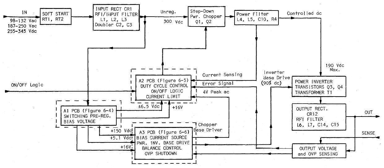
[3] For full details on the power supply operation, see the block diagram. First, the 115V AC line input is converted to 300V DC by a rectifier and voltage doubler. (The voltage doubler is a clever way of supporting both 115V and 230V inputs; using the doubler with 115V. This is why older PCs have a switch on the power supply to select 115V or 230V. Modern power supplies handle a wide input range, and don't require a switch.) Next, the power supply has a chopper, a PWM transistor circuit that chops up the 300V DC, producing a regulated 120V-200V DC, depending on the output load. This goes to the inverter, which drives a step-down/isolation transformer that produces the desired 15V output. A regulation circuit sends feedback to the chopper based on the output voltage. Meanwhile, an entirely separate switching power supply circuit generates voltages (including +150V) used by the power supply internally.
Modern power supplies use a single switching stage in place of the separate chopper and inverter. I believe the two stages were used to reduce the load on the bipolar switching transistors, which don't have the performance of modern MOSFET switching transistors. (As Ron pointed out, modern power supplies often have a PFC (power factor correction) stage for improved efficiency. Thus, the two-stage design has returned, although the stages are entirely different now.)
Modern power supplies use a power supply control IC. The Alto's power supply instead has control circuits built from simple components: transistors, op amps, 555 timers. This is one reason the power supply requires three circuit boards.
[4] The following table from the Alto disk manual gives the stats for the drive.

[5] The Alto backplane has 21 slots, not all of which are used in our system. The list of which board goes into which slot is on page 8 of the Alto documentation.
[6] I suspect that the Y Combinator Alto originally had both a Trident drive and a Diablo drive (as well as four Orbit boards to drive a laser printer), and when it was taken out of service, the Trident drive, the Diablo interface board, and the Orbit boards went off somewhere else. This left the Alto with a drive that didn't match the interface card.
For reference, schematics and documentation on the Trident interface board are here. Despite all the chips on the disk interface board, it doesn't do very much, since each TTL chip is fairly simple. The interface board has some counters, one word data buffers, parallel/serial conversion, and a bit of control logic. The Alto was designed to offload many hardware tasks to microcode, so the hard work of disk I/O is performed in microcode (software).
6 comments:
Any thoughts as to why all 3 capacitors in only one power supply had gone bad, while the other supplies were still fine?
Interesting question Dan. We saw some internal repairs on the faulty power supply, so it must have had some malfunction in the past. This might have damaged the capacitors (overheated? overvoltage?) causing them to fail sooner. Although it's possible that the capacitors in the other supplies are bad but not bad enough yet to cause visible problems.
I would probably replace the electrolytic caps with modern, low ESR ones as a matter of course. They are most likely dried out after all those years and could cause the PSU to malfunction under load. I strongly suggest checking them with an ESR meter at least.
If you want to keep the stock look, you can always gut the original cans and put a modern capacitor inside. They will certainly be smaller than those period monsters.
Actually Ken, only two caps where bad, the two big silver ones. The main caps after the first rectifier stage, both identical.
Marc
Congratulation !!!
You are best in the best.
Most interesting. And great work. The power supplies always seemed to cause trouble, even back in the day. One of my 12 V supplies suddenly stopped working one day last year. Turns out it had a bad 390 pF silver-mica cap that took out the 680 ohm 5 watt resistor next to it in the Q3/Q4 inverter drive. The resistor was fried to a crisp. Replacing those two parts restored proper operation. I tested the big cans and they were still good so I just left them there.
Those power supplies are a real pain to work on, with their convoluted folded-up origami layout.
Post a Comment