For background, the Alto was a revolutionary computer designed at Xerox PARC in 1973 to investigate personal computing. It introduced the GUI, Ethernet and laser printers to the world, among other things. Y Combinator received an Alto from computer visionary Alan Kay and I'm helping restore the system, along with Marc Verdiell, Luca Severini, Ron Crane, Carl Claunch and Ed Thelen. The full collection of Alto restoration posts is here.
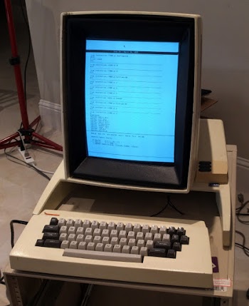
To assist with debugging, the Alto includes a debugger called Swat. If a program malfunctions, it drops into the Swat debugger, as seen above. The debugger lets you examine memory and set breakpoints. It is more advanced than I'd expect for 1973, including a feature to disassemble machine instructions from memory and view them with names from the symbol table.
In our case, the debugger showed that when we ran the MADTEST test program, the Alto had jumped to address 2, which triggered the debugger. The first 8 memory locations in the Xerox Alto contain TRAP instructions to catch erroneous jumps to a zero address (or near-zero address) which can happen if a subroutine return address is clobbered. By examining the stack frames, I determined which subroutine had been called when the system crashed. The problem occurred when the program was jumping to microcode that had been loaded into microcode RAM, Since this is an unusual operation, it would explain why most programs ran successfully and only a few crashed.
Microcode
Microcode is a low-level feature of most processors, but I should explain what it means for a program to jump to microcode, since this is a strange feature of the Alto. Computers execute machine code, the simple, low-level instructions that the CPU can understand; on modern computers this may be the x86 instruction set, while the Alto used the Data General Nova instruction set. Most processors, however, don't run machine instructions directly, but have a microcode layer that is invisible to the programmer. While the processor appears to be running machine instructions, it internally executes microcode, a simpler, low-level instruction set that is a better match for the hardware. Each machine instruction may turn into many micro-instructions.The Xerox Alto uses microcode much more extensively than most computers, with microcode performing tasks such as device control that most computers do in hardware, resulting in a cheaper and more flexible system. (As Alan Kay wrote, "Hardware is just software crystallized early.") On the Alto, programmers have access to the microcode—a user program can load new microcode into special control RAM. This microcode can implement new machine instructions, optimize particular operations (analogous to GPU programming), or obtain low-level control over the system.
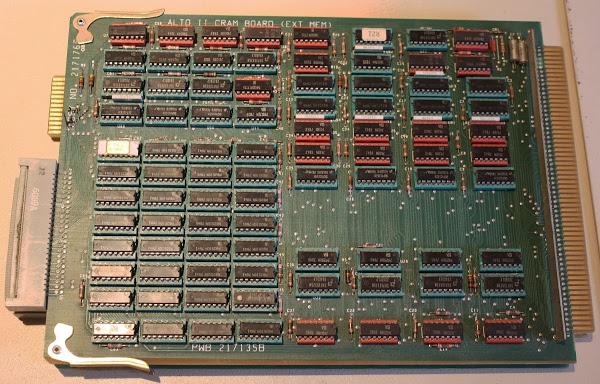
Our Alto has 1024 words of microcode in ROM (for the standard microcode) and 1024 words in RAM (for software-controlled microcode). The photo above shows the CRAM (control RAM) board that holds the user-modifiable microcode. This board illustrates the incredible improvements in memory density since 1973—this board required 32 memory chips to hold the 1024 32-bit words (4 Kbytes) of microcode.
The Alto's microcode uses a 1K (10-bit) address space. Since Altos can support up to 2K of microcode in ROM and 3K in RAM, bank switching is used to switch between different 1K memory banks. Bank switching is triggered by a special micro-instruction called SWMODE (switch mode).
Getting back to our crash, the MADTEST test program loads special test microcode into the control RAM. Then it executes the JMPRAM machine instruction to switch execution from machine instructions to the microcode in RAM. The microcode that implements JMPRAM performs a SWMODE to switch execution to the RAM microcode bank and the microcode in RAM will execute. When the microcode is done, it is supposed to return execution to the machine code emulator, and execution of the user-level program (MADTEST) will continue. But somehow execution ended up at address 2, causing the program to crash.
We used a logic analyzer to record every micro-instruction and memory access, so we could determine exactly what went wrong. After a few tries, we captured a trace showing what the Alto was executing until it crashed. Over the past week, I've been using the Living Computer Museum's ContrAlto simulator of the Xerox Alto to understand how the Alto's software and microcode work. With this background, I could interpret the logic analyzer output and map it to the MADTEST code and the microcode. Everything proceeded fine until the JMPRAM instruction was executed. Instead of switching to the microcode in RAM, it was still running microcode from the ROM. Since the micro-address was intended for the RAM code, the processor was running essentially random microcode. Through pure luck, this microcode routine completed and returned control to the regular machine code emulator rather than hanging the system. Unfortunately this code didn't load the return address register, resulting in a jump to address 2 and the Swat crash we saw.
To summarize, everything was working fine except instead of switching to the microcode RAM bank, execution stayed in the microcode ROM bank. This was pretty clearly a hardware problem, so we started looking at the bank switch circuit, which consists of multiple integrated circuits.
The bank switch hardware
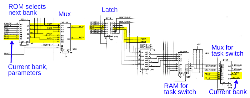
The Alto was built at the dawn of the microprocessor age, so instead of using a microprocessor chip, it used three boards of TTL chips for the CPU. The control board interprets the microcode, including performing bank switching, so that's where we started our investigation.Bank switching in the Alto happens when the SWMODE micro-instruction is executed. The destination bank is selected following complex rules that depend on the hardware configuration and the current bank. Rather than implement these rules with a complex hardware circuit, the Alto designers used the short cut of encoding all the logic into a 256x4 PROM chip. (This also has the advantage that a different hardware configuration can be supported simply by replacing the PROM.) The schematic below shows the PROM (left) generating the bank select signals (yellow), which pass through various chips to create the current bank select signals (right), which are fed back into the PROM for the next cycle.
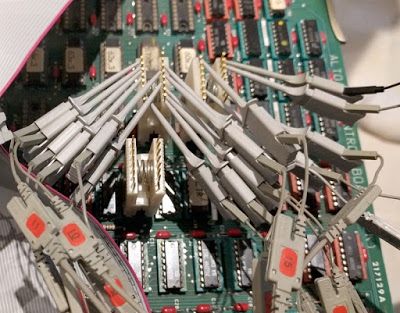
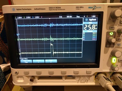
We connected logic analyzer probes so we could trace each chip in the bank select circuit. The PROM correctly generated the RAM bank signals when the SWMODE micro-instruction executed, but in the next step its inputs had reverted to the ROM bank for some reason. This showed the PROM worked, so we continued probing through the circuit. Each chip had the proper output until we got to the multiplexer chip that feeds back to the PROM. (This chip, on the right, handles microcode task switching by selecting either the current task's bank, or the new tasks's bank, which is recorded in a RAM chip.) The input signal to the multiplexer pulsed high for the new bank, but the output stayed low, blocking the bank switch signal. The oscilloscope trace below shows the problem: the input signal (bottom trace) is not passed to the output (middle trace).
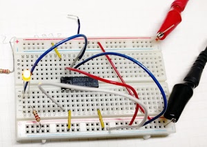
We found a bad chip on the disk interface board a few weeks ago, so had we located a second bad chip? We pulled out the suspicious chip (a 74S157 multiplexer) and tested it in a breadboard to prove that it was faulty. Surprisingly, it worked just fine. Perhaps the problem only showed up at high frequency? We swapped it with an identical chip on the board and the crash still happened. Clearly there was nothing wrong with the chip. But its output stayed low when it should go high. Why was this?
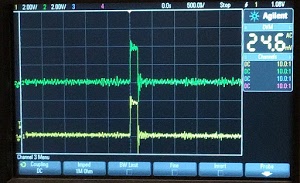
Our next theory was that something was grounding the chip's output signal, forcing the output to remain low. To test this, we disconnected the chip's output pin from the rest of the circuit by bending the pin so it didn't go into the socket, With the output not connected to the circuit, the output went high as expected. (See oscilloscope trace below.) This proved that the chip worked and something else was pulling the signal low. Since the chip's output was connected to the PROM chip, the obvious suspect was the PROM, which might have an input shorted low. We hoped the PROM chip wasn't at fault, since locating a 1970s-era D3601 PROM chip and reprogramming it would be inconvenient. We pulled the PROM chip out of the board and the short to ground remained, demonstrating the PROM chip was not the culprit.
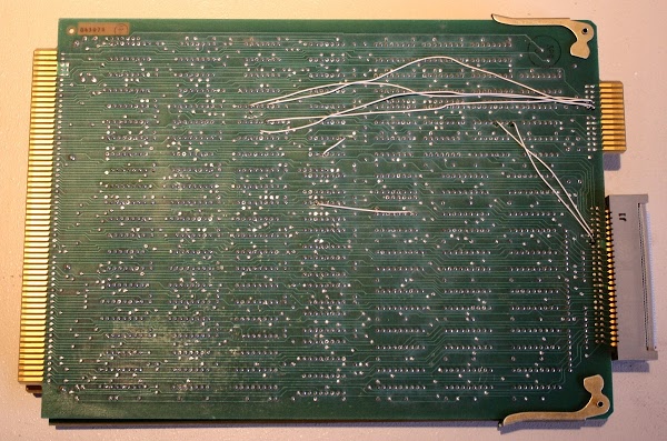
We removed the control board from the Alto to examine it for short circuits. On the back of the circuit board, we noticed that two white wires were connected to the multiplexer chip that was causing us problems. (Wires are added to printed circuit boards to fix manufacturing problems, support new features, or support new hardware.) These wires went to the connector that was cabled to the CRAM (control RAM) board shown earlier. With the CRAM board disconnected, the short to ground went away. Thus, the cause of our crashes was these two wires that someone had added to the board! Could we simply cut these wires and have the system work correctly? We figured we should understand why the wires were there, rather than randomly ripping them out. Maybe our control board and CRAM board were incompatible? Maybe these wires were to support the Trident disk drive we aren't using? It was the end of the day by this point, so further investigation will wait until next time.
Conclusion
After a bunch of software, microcode and hardware debugging we found that the crashes are due to some wires added to one of the circuit boards. These wires messed up microcode bank switching, causing programs that used custom microcode to crash. Fixing this should be straightforward, but we want to understand the motivation behind these wires. On the whole, the processor is working reliably other than this one issue. Once it is fixed, we can run MADTEST (the microcode test program) to stress-test the processor. If there are no more processor issues, we'll move on to getting the mouse working.For updates on the restoration, follow me on Twitter at kenshirriff. Thanks to the Living Computer Museum for the extender board and the ContrAlto simulator.
3 comments:
Great work guys! You are squashing bugs at an impressive rate.
I have been closely following your progress and will be happy to see your next update!
Nicely documented. Can't wait for the next installment!
I have an Alto mouse, but nothing to connect it to! A smaller slice of history.
Post a Comment