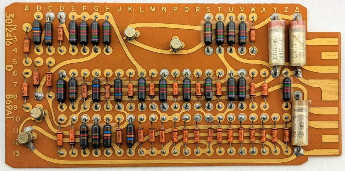
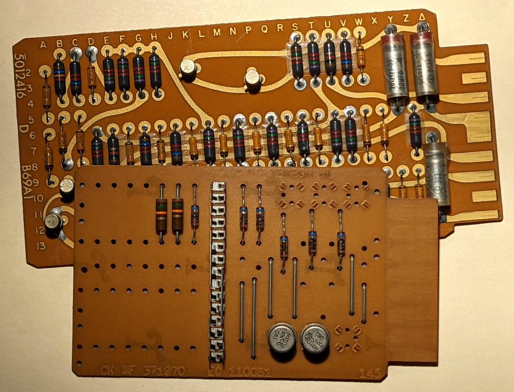
The IBM 1401 team at the Computer History Museum accumulates a lot of mystery components from donations and other sources. While going through a box, we came across the unusual circuit board below. At first, it looked like an IBM SMS (Standard Modular System) card, the building block of IBM's computers of the late 1950s and early 1960s.1 However, this board is larger, has double-sided wiring, the connector is different, and the labeling is different.2
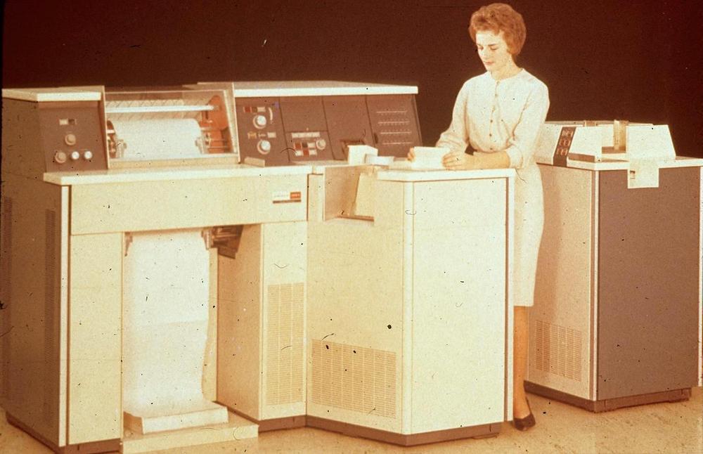
I asked around about the board and Robert Garner identified it as from the Univac 1004, a plugboard-controlled data processing system from 1963.4 The Univac 1004 was marketed as a "Card Processor" rather than a computer,3 designed for business applications that read punch cards and producing output, but still required calculation and logical decisions. Typical applications were payroll, inventory, billing, or accounting.
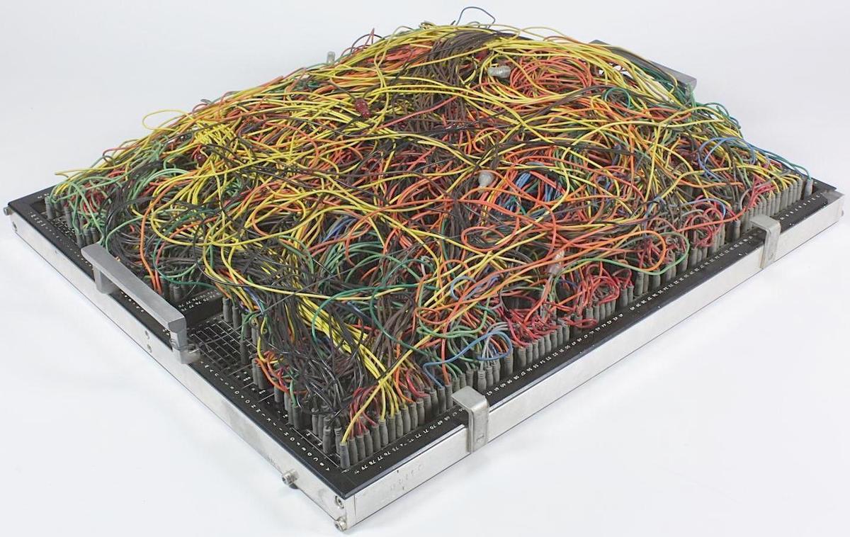
The most unusual feature of the Univac 1004 was that it was programmed by a plugboard (below) instead of a stored program. The system was programmed by plugging patch cords into a plugboard to indicate the desired action for each of the 31 program steps. While earlier electromechanical accounting machines used plugboards, they were pretty much obsolete by 1963, so I was a bit surprised to see plugboards still in use.
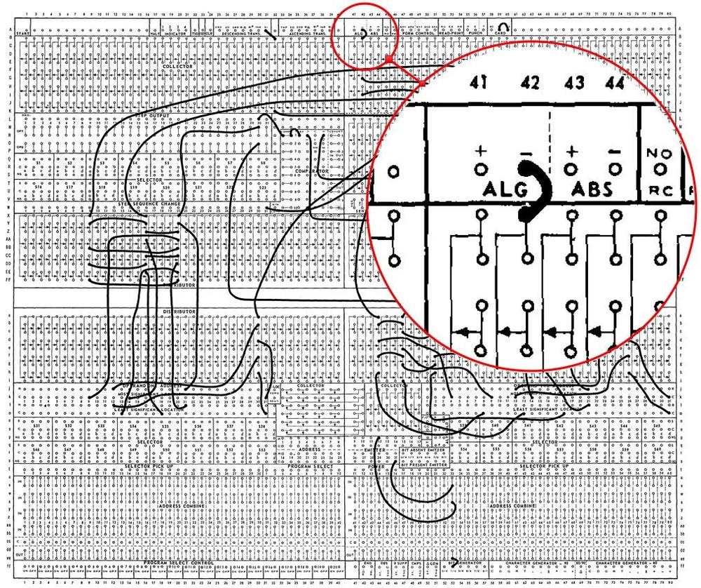
The computer's "program" consisted of 31 steps. The operations for each step were specified by plugging wires into the board. For instance, a data field could be moved from a punch card to memory, a value could be added or subtracted, or a line of output could be configured for the printer.5 The system even supported conditional branches. The diagram below shows the structure of the plugboard. The highlighted wire shows a subtraction operation, activated by the wire in the "algebraic minus" position.
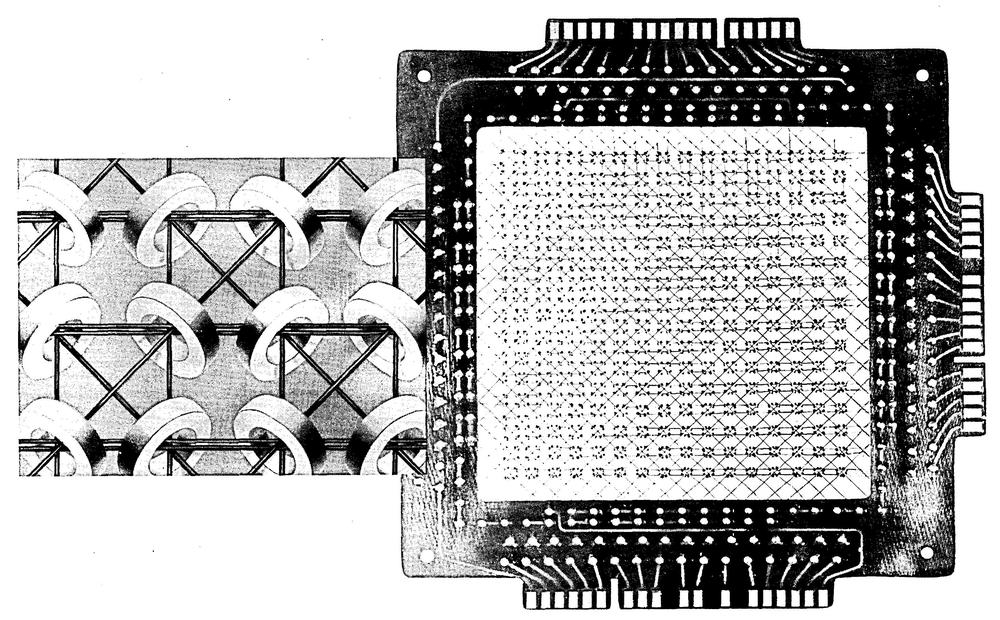
The computer had a small memory of 961 6-bit characters. Like most computers of the era, it used magnetic core memory, storing each bit by magnetizing a tiny ferrite ring. Note that since the computer was programmed through a wiring panel, none of the memory was used for program code.
While the Univac 1004 was primitive for its time compared to even a low-end business computer like the IBM 1401, it had a few advantages. First, it rented for $1900 a month, compared to $2500 a month for the IBM 1401 (about $18,000 vs $23,000 a month in current dollars). Second, the Univac computer was compact (by 1960s standards), weighing 2500 pounds. Finally, many customers found plugboard programming easier than programming with code, both because they were more familiar with it and because it is visual and direct.
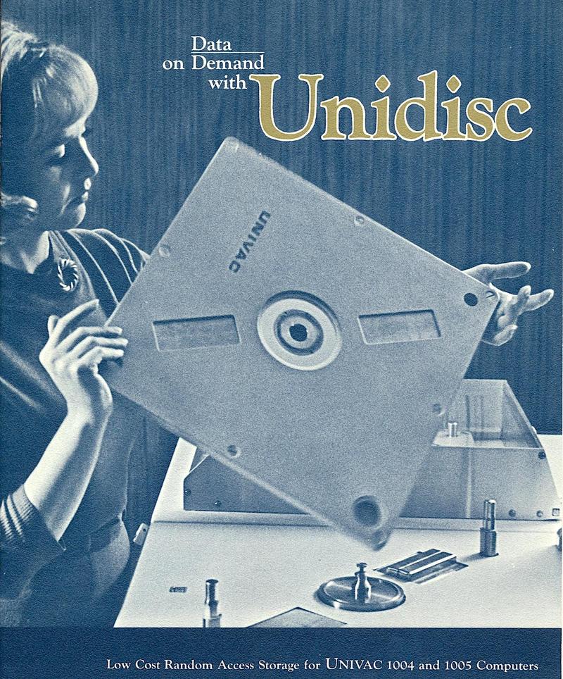
The Univac 1004 could be extended with peripherals such as tape drives, a card punch, or disk storage. The photo below shows the Unidisc cartridge, which held one million characters. Although it looks like an absurdly-large floppy disk, it was a removable hard disk.
Reverse-engineering the board
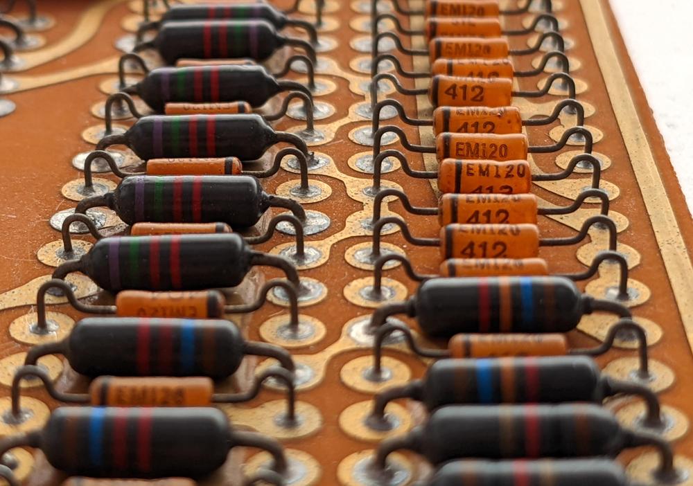
The function of the board wasn't immediately obvious and we had various theories of what it might do. To find out, I reverse-engineered the board by tracing out the circuitry.6 The board has 32 diodes, which seems like a lot, as well as resistors, transistors, and capacitors. The transistors are not silicon transistors, but germanium PNP transistors.
The board turned out to be a logic board implemented with AND-OR-INVERT logic.7 That is, various inputs are ANDed together, the AND results are then ORed together, and finally the result is inverted. The board is implemented with diode-transistor logic. One layer of diodes implements the AND gates and the second layer of diodes implements the OR gates. Finally, a transistor amplifies the result, inverting it in the process. Diode-transistor logic (DTL) performed better than earlier resistor-transistor logic (RTL), but was soon replaced by transistor-transistor logic.
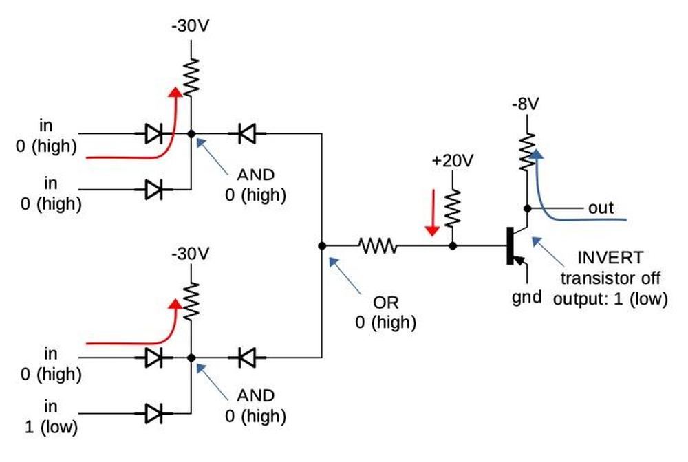
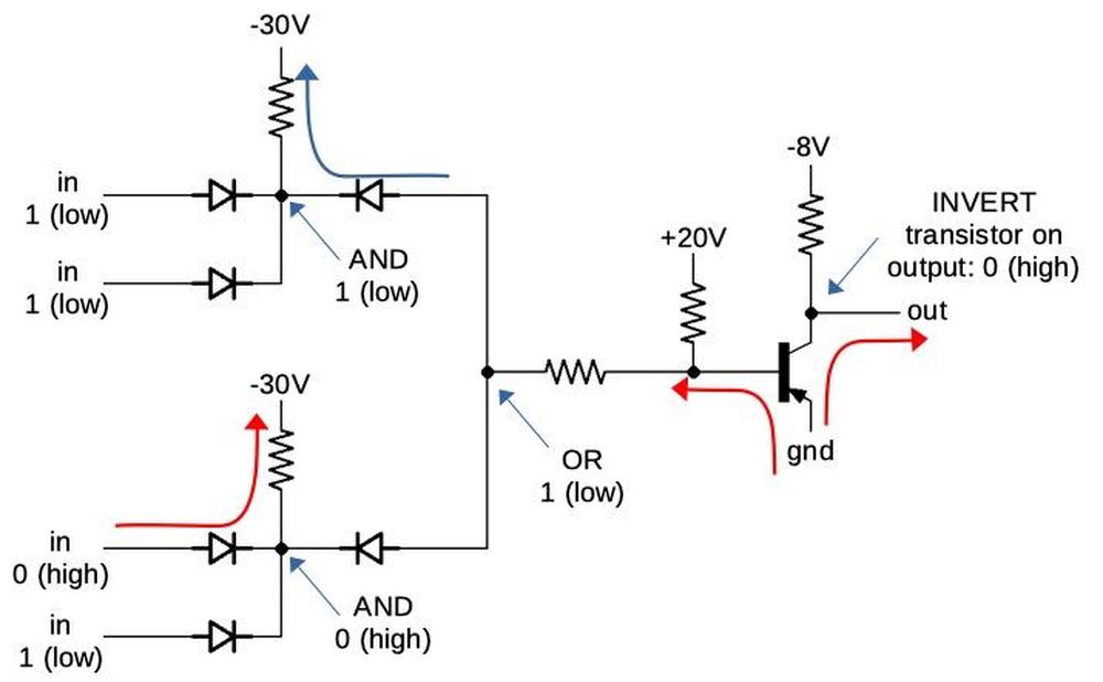
The diagram below explains how the AND-OR-INVERT logic was implemented. This circuit has four inputs: two AND gates that are then ORed together and inverted. (It's a bit confusing because the circuit uses active-low logic, so the voltage levels are all inverted.) If the AND gates all have a 0 (high) input, a diode in the first stage will conduct and pull the AND node high. This blocks the diodes in the second stage (which have the opposite orientation), so the OR node is also high. In the INVERT stage, the +20V resistor will pull the transistor's base high, which turns it off (since it is PNP). Finally, the -8V resistor will pull the output low (i.e. 1), providing the desired AND-OR-INVERT logic.
The diagram below shows that if the first AND gate's inputs are 1 (low), the first diodes are blocked, so the -30V resistor pulls the AND node low (1). Now the second-stage diode conducts, pulling the OR node low (1). This allows base current to flow through the PNP transistor, turning it on. This pulls the output high (0). (Note that ground is a high output compared to the low output of -8V.) The gates on the board have more inputs, but use the same principle.
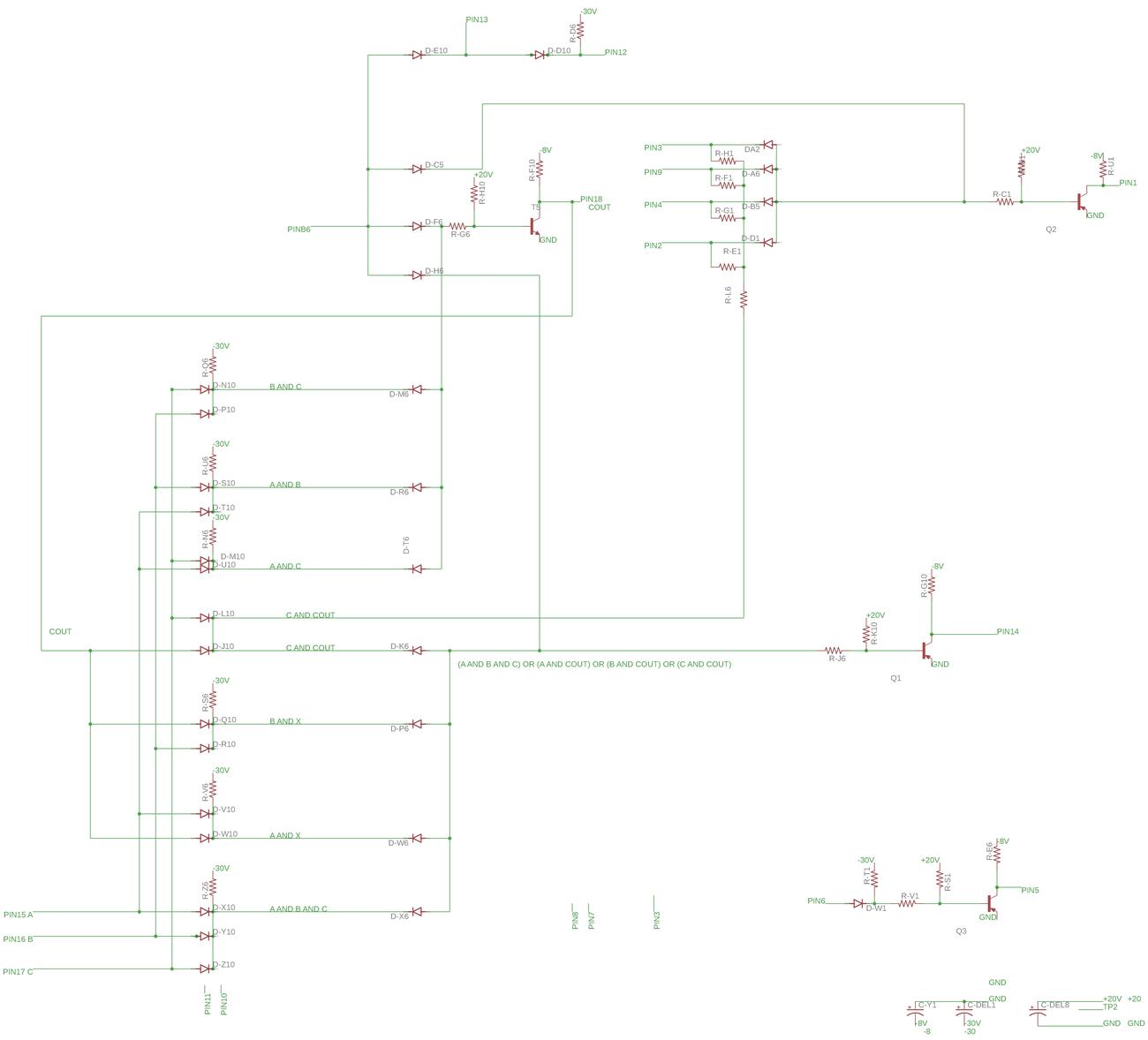
After tracing out the board's logic, I recognized that it implemented a full adder.8 That is, it adds two input bits along with a carry-in, producing a sum bit and a carry-out. By connecting four full-adders in series, a 4-bit value can be added, allowing one decimal digit to be added. Thus, the computer probably has four one-bit adder boards similar to this, along with circuitry to convert the output from binary to binary-coded decimal.10
The board has a few additional circuits along with the full adder circuit. It includes an inverter circuit. The board also has 4 inputs that are ANDed, subject to the carry value. Finally, the board also has a disable input that blocks the outputs.9 Without knowing more about the circuitry, I can't determine the role of these circuits.
Conclusion
The mystery circuit board turned out to be from the Univac 1004. Although this computer was produced in the 1960s, its technology occupies an interesting location between the electro-mechanical accounting machines of the 1940s and the electronic business computers of the late 1950s. The Univac computer used transistors and core memory, but it kept the earlier plugboard programming of the accounting machines, rather than moving to stored-program computing (introduced in 1948). Even though the Univac 1004 was technologically backward for 1963, businesses flocked to it, making it the second-most popular computer at the time with 3400 installations.4
This shows that progress isn't as linear as you might expect; "obsolete" technologies can continue to thrive long after the introduction of "superior" alternatives such as stored-program computing. Instead, new systems can still be developed with supposedly-obsolete technologies, depending on the tradeoffs involved.
I announce my latest blog posts on Twitter, so follow me @kenshirriff. I also have an RSS feed.
Notes and references
-
The Computer History Museum links to a similar board. ↩
-
The photo below compares the Univac board to a smaller IBM SMS board.
Comparison with an IBM SMS card. -
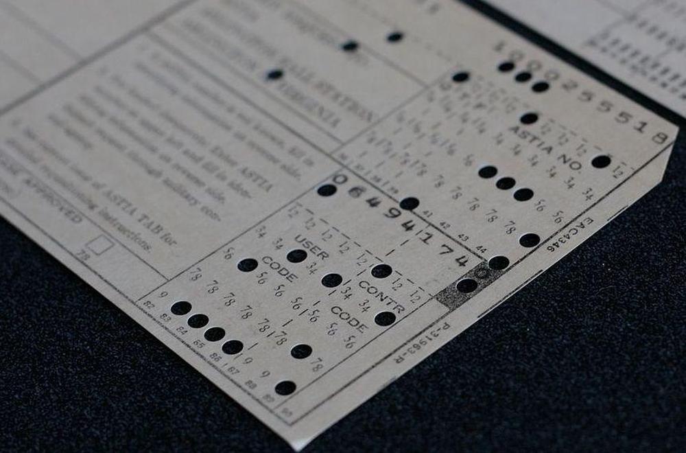
The Univac 1004 computer came in two versions. The "80" read standard IBM 80-column punch cards. The "90" read Univac's 90-column cards (details), which held 90 characters per card instead of 80. The 90-column card was introduced in 1930 by Remington Rand. It had round holes instead of IBM's rectangular holes. The card stored two characters per column by using a denser, binary code. Despite the superior capacity of the 90-column card, IBM's 80-column cards dominated the market. (Even IBM couldn't displace the 80-column card, although they tried with the 96-column card that they introduced in 1969.)
A 90-column punch card. From Marcin Wichary, (CC BY 2.0). -
Robert Garner discusses the Univac 1004 briefly in his article on Early Popular Computers. More information is in the 1964 BRL report as well as on Bitsavers. A related board from the Univac 1040/1050 is described here. ↩↩
-
The plugboard supported conditionals and looping, so I think the system was Turing-complete, although you couldn't do a lot in 31 programming steps. You could implement multiplication or division with a short shift and add (or subtract) loop. ↩
-
To reverse-engineer the board, I took photos of both sides, flipped the image of the back in GIMP so the two sides were aligned visually, arranged the components on a schematic in EAGLE, and connected the components to match the circuit board. Then I moved the components around until the layout made sense.
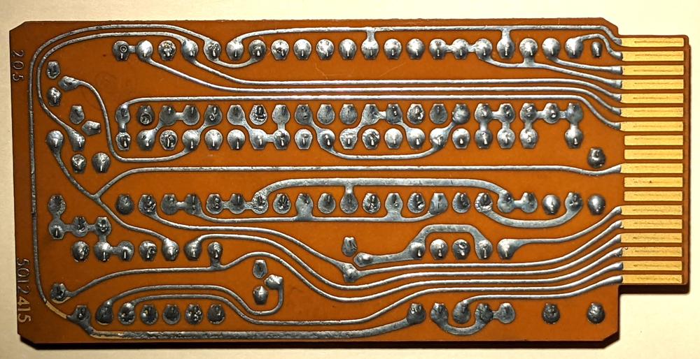
The underside of the circuit board.The back of the circuit board is shown above. Note that the edge connectors are completely different on the two sides of the board.
-
AND-OR-INVERT logic was also used in the IBM System/360 computers, although it was built from hybrid SLT modules instead of discrete components. ↩
-
I suspected the board was an adder when I saw that it had three inputs and was combining them symmetrically. The full adder is implemented in AND-OR-INVERT logic as follows. If the two bits are A and B and the carry-in is CIN, then a carry-out (COUT) is generated if at least two input bits are set. This is computed by the AND-OR logic "(A and B) or (A and CIN) or (B and CIN)". The sum bit is set if there is a single 1 input or three 1 inputs. The sum bit was computed by "(A and not COUT) or (B and not COUT) or (CIN and not COUT) or (A and B and CIN)" As a result of the AND-OR-INVERT circuit, the output is inverted. The inverter circuit on the board was probably used to un-invert it. ↩
-
The full reverse-engineered schematic is below.
Reverse-engineered schematic of the board. Click for a larger version. -
The computer uses excess-three encoding for digits, adding 3 to the value before converting to binary. For example, 6 is represented as binary 1001. The advantage of this encoding is that flipping the bits yields the 9's-complement decimal value, simplifying subtraction. For example, flipping the bits of 6 yields binary 0110, which is 3 in excess-3 notation. Excess-3 representation also handles carries correctly; if you add two numbers that sum to 10, the excess-3 values will sum to 16, causing a binary carry. To convert the sum to excess-3, The value 3 must be added (if a carry) or subtracted (if no carry).
To see how addition works with excess-3, 2 + 4 in excess-3 is binary 0101 + 0111 = 1100. Subtracting 3 yields 1001, which is 6 in excess-3. But 2 + 9 is binary 0101 + 1100 = 10001, generating a carry out of the 4 bit value. Adding 3 yields 0100, which is 1 in excess-3. Considering the carry-out, this is the desired result of 11. ↩
25 comments:
I worked for Univac and had occasion to work with the 1001 card reader. The 1004 was also popular as a RJE (Remote Job Entry) and printer attached to the more powerful 1100 series computers.
The unit behind the female operator is a row card punch (200 cards/min.)
Holy moly! Can you imagine debugging that mountain of spaghetti? What if one of those wires developed an intermittent open? Makes me glad I just missed that era.
so cool and interesting.
I like the methods of using Eagle cat for reverse engineering. I wondered if there was any dedicated software any knows about? I was doing something similar the other day using flood fills for ground and supply and I roughly knew what it was going to look like but it was still a pain.
Fun read!
You mentioned that this is a 2-sided board. Does it employ plated-thru holes or do they rely on component leads to join the traces on both sides?
Also, the inline circuit diagrams show PNP transistors but the Eagle schematic shows NPN. It would seem that PNP is correct based on the negative Vcc.
Thanks for shedding light on this early technology.
-Rob
Rob: all the holes have component leads in them, so I can't tell if they are plated-thru or not. You are correct about the schematic; I have fixed it.
I recall programming a Univac 1108 at the Univ of Wisconsin in the late 1960s and early 1970s. It was run by the statistics department.
IIRC the 6 bit character set may have been called 'SDF', but I don't recall what that stood for. However, 6 of them would fit perfectly in the 36 bit word that the 1108 had. There were some instructions (or addressing modes) that would pick apart such a character 'string'.
(we also had a PDP-8, a Datacraft machine, and a Burroughs 5500 or 6500 (stack oriented architecture on Burroughs)
Attn: George Byrkit,
The Univac 1108 family (1106, 1108, 1110, 1100/10, 1100/20, 1100/60, 1100/80 and beyond) used Fieldata (six-bit code, 3-binary digit octal characters, six characters to a 36-bit word) of only uppercase, numerics, some special characters, and barely any data control characters (CR/LF) as its native encoding. 7-bit ASCII characters were mapped over the 36-bit word as four 9-bit characters to the word with "stop-bits" (individual character "sign" bit, if you like) to indicate end of character encoding so that byte channel controllers (as opposed to word channel controllers (disk and drum)) knew when to terminate byte sequenced transfers.
Also, the Univac 1100 series was a ones-complement computer utilizing Octal representation throughout (manuals and even dumps) with all machine instructions occupying single words, although there were some doubleword operations against storage, I.E.: double-word shifts and double word floating point.
Attn: Michele,
When a wire was broken and it wasn't "intuitively obvious" we would have to resort to trouble-shooting it with an Ohm meter to find the errant wires, often turning the board upside down and back over again multiple times in our quest.
Attn Stephen Hubbard:
Thank you very much for the additional data. Yes, 'Fielddata' it was. Ditto on the ones-complement arithmetic. The one I had access to had IIRC disk, tape, drum, and cardread/punch. Much like an RJE station.
I have an original printed copy of the reference manual for the 90-column version of the Univac 1004. The machine has always fascinated me. I've been toying with the idea of implementing an emulator for it, so I could try my hand at programming it.
I've seen a few references to an extremely complicated plugboard program for the 1004, called "Emulator", that effectively turned it into a stored-program computer would read a program from punched cards and run that. I can't even begin to imagine how that could be done with 31 program steps and 961 words of memory. But apparently it was very popular. People would wire up an "Emulator" plugboard, plug it in, and never need to change it ever again.
If anyone knows where the details for making an Emulator plugboard could be found, I'd appreciate it.
Fantastic read, I have a similar card which I posted on Reddit: https://www.reddit.com/r/vintagecomputing/comments/zblvv0/comment/iytk4vp/?context=3
Would be curious to see what your thoughts are on it.
As a young consultant programmer in the UK in 1964 I programmed the payroll system for a manufacturing company on a Univac 1004. My previous project was an invoicing system on a British clone of the RCA 501 with 48K of memory (wow!) so having only 1K and a limit of 31 instructions presented some challenges. I think I was able to get the payroll system into five programs (or plugboards) with the final program calculating how many five and one pound notes, half-crowns, shillings, etc would be required for each worker's pay packet (employees were assumed not to have bank accounts). I remember how much fun the programming was!
Hi,
I have the original documentation for that board and the 1040 (!) computer it came from. Around 1975 (age 15) I tried to build an 18 bits computer with it. The 18 bits ALU worked, but I got stuck on connecting incompatible BULL core memory. Not much later I got my hands on an 8080 chip and the project was abandoned. However, board and part completed backplane still sit in my garage. Happy to provide photo's.
Marcel
I apologize. This is a B series board that came from 2202 dual card punch. The 1040 computer used shorted A series boards. In my design I combined the two. Marcel
The Univac 1004 with an emulator board, allowing executing programs from punched cards, was in fact marketed as the Univac 1005.
I worked nights while in college as a computer operator on a Univac 1005. Ut had a large special plug board that turned the 1004 into the 1005. This allowed processing special rpg programs instead on special plug boards (we had special plug boards for certain reports).
Ken Shirriff's blog is a treasure trove of knowledge! The detailed insights and thorough explanations make complex topics accessible and engaging. I appreciate the effort put into each post, providing readers with valuable information and sparking curiosity. Keep it up!
Posting a message for a 96 year old reader:
"I started out as a U.S. Army Tabulating Machine Operator in 1947. In about 1970 I was working as a private consultant in San Francisco for IBM installations. One of the individuals I used to help out was an ex Univac programmer that was about my age. One time he left a Univac Plugboard with me and never picked it up. I later learned he found a full-time job in an IBM installation and severed all connections to consulting work. He had told me that it was an Emulator Board that an Ex Univac-engineer had developed. On several occasions I have been tempted to drop the board off at the dump but just couldn’t do it. Review of your blog confirms that it is in fact a 1004 board and looks identical to the picture you show. In fact, my experience is that no single application plugboard requires as many wires as shown in your picture, and in my board. Therefore, I think your picture of an application board is actually a 1004 emulator board that could have been used for payroll processing. Although, according to what I read, emulator processing was hard on internal selectors of the 1004."
It's a long time ago, but I wrote a payroll program for the 1004 in 1963 (I think) in the UK. It was actually 3 programs, but the third was only a computation of the least number of coins (pennies, sixpences, shillings, etc) needed in an employee's pay packet to make up his/her pay. My recollection is that at least one of the programs looked much like the picture!
Does that reader still have his Emulator board? I would love to get my hands on one, and maybe reverse engineer it. As I said above (anonymously), I have a hard time imagining how it could possibly work. Maybe some active logic is included, buried under all those wires?
It's probably not important in the grand scheme of things, but I would hate for the knowledge to be lost to time.
So cool! In 1968, I went to a technical high school because my dad really wanted me to ¨get into computers¨ as he saw it as the future of all things to come. The spaghetti board typified our school technology. The instructor was in love with the damn thing. It looked like a washing machine to me and for the life of me, I had no idea how programming was to be done with all those wires to be plugged in and out. I was a terrible typist too and could never get my punch cards to run anything. I gave up and tried to get into Surveying but back then ¨girls¨ weren´t allowed in the program because you had to wear jeans in the field. I´ve often wondered what that thing was that I had tried to program so it was really great to find the pictures. Thanks!
I was apprenticed at the plant of Remington Rand UNIVAC in Frankfurt-Rödelheim during the sixties to become a mechanic. That time most of the data processing still was mechanical. The finish of all the equipment was dominated of a dark grey curling varnish.
After finishing my apprenticeship period I made a training course about the 1004 logic (3-xcess code) to further work in the final test: Several test programs - each on a plugboard - had to be run until the procedure finished with no errors (of course).
During the production process the units were standing on rollable platforms which were lifted about 30cm and all the doors still were not yet installed. With two huge fans placed on the back and on the right the electronic was kept cool. Each colleague had his small rolling stool and a huge tektronix osci to fetch the existing errors. Faulty electronic cards could be replaced from a stock of spare cards.
For the card reader I remember an interesting feature: it was capable of reading 90 column and 80 column cards. The division was made by a magnetic wheel coupled to the transport wheel and several adjustable reading/writing heads.
The printer unit which came preassembled from US existed in 2 speed variants, the printing process was divided in odd and even columns because of the current consumption.
The subsequent model to the 1004, was the 1005, which saw major usage in US Army installations. It was no longer plug board based and had an assembler that produced a runnable binary deck. I had a opportunity to program the 1005 in the 1970 time frame at Fort Benjamin Harrison outside Indianapolis Indiana. Opened some doors to a follow on position at my next station.
Fan of Ken's work on the Apollo AGC, with that whole ingenious team.
I worked at ICL at Artarmon in Sydney Australia for several years back in the 1970`s. We used the 1004 for various accounting tasks. As workshop supervisor, I was given the use of it to create analysis programs for various computer board faults with quite good results (basically statistical analysis). When it was scrapped, I was given it for use developing UFOCOMFILE, a system of cataloguing and sorting UFO sightings. I eventually move it to a 1904 but those formative plug wire wiring program sessions were most enjoying and extremely easy to implement. With the on board relays available, I was able to program 62 steps with many branches. Needless to say that the board was absolutely choked with wires and weighed a ton. Fantastic memories for me. I am currently working on a relay implementation of a BR133 but making it 16 instead of 15 bits. All the best.
Post a Comment