
A voltage regulator takes an unregulated input voltage and converts it to the exact regulated voltage an electronic circuit requires. Voltage regulators are used in almost every electronic circuit, and the popular 7805 has been used everywhere from computers[1] to satellites, from DVD player and video games to Arduinos[2]. and robots. Even though it was introduced in 1972 and more advanced regulators[3] are now available, the 7805 is still in use, especially with hobbyists.
The 7805 is a common type of regulator known as a linear regulator. (As its name hints, the 7805 produces 5 volts.) A linear regulator is built around a large transistor that controls the amount of power flowing to the output, acting similar to a variable resistor. (This transistor is visible in the right half of the die photo above.) A drawback of a linear regulator is that all the "extra" voltage gets converted into heat. If you put 9 volts into a linear regulator and get 5 volts out, the extra 4 volts gets turned into heat in the regulator, so the regulator is only about 56% efficient. (The main competitor to a linear regulator is a switching power supply - a much more efficient, but much more complicated way to produce regulated voltage. Switching power supplies have replaced linear regulators in many applications, such as phone chargers and computer power supplies.)

Linear regulators such as the 7805 became very popular because they are extremely easy to use: just feed the unregulated voltage into one pin, ground the second pin, and get regulated voltage out the third pin[4]. Another feature that made the 7805 popular is it is almost indestructible - if you short-circuit it, put too much voltage in, or run it too hot, it will shut down before getting damaged, due to internal protection circuits.
The components of the integrated circuit
Like most chips, the 7805 is built from a tiny piece of silicon. To make the chip function, a process called doping treats regions of the silicon with elements such as phosphorus or boron. In the die photo, these regions have a slightly different color, which makes the structure of the chip visible. Phosphorus gives the region excess electrons (i.e. negative), so it is known as N silicon. Boron has the opposite effect, creating positive P silicon. The amount of doping in a silicon chip is surprisingly small, varying from 1 foreign atom for every thousand atoms of silicon down to one foreign atom per billion atoms of silicon. Because silicon is so sensitive to impurities, the original silicon wafer must be an insanely pure crystal, up to 99.999999999% pure - a level known as eleven nines.On top of the silicon, a thin layer of metal connects different parts of the chip. This metal is clearly visible in the die photo as white traces and regions.[5] A thin, glassy silicon dioxide layer provides insulation between the metal and the silicon, except where rectangular contact holes in the silicon dioxide allow the metal to connect to the silicon. Around the edge of the chip, thin wires connect the metal pads to the chip's external pins - the black blobs in the photo show where the wires were attached.
Transistors inside the IC
Transistors are the key components in the chip. The 7805 uses NPN and PNP bipolar transistors (unlike digital chips which usually have CMOS transistors). If you've studied electronics, you've probably seen a diagram of a NPN transistor like the one below, showing the collector (C), base (B), and emitter (E) of the transistor, The transistor is illustrated as a sandwich of P silicon in between two symmetric layers of N silicon; the N-P-N layers make a NPN transistor. It turns out that transistors on a chip look nothing like this, and the base often isn't even in the middle!

The photo below shows one of the transistors in the 7805 as it appears on the chip.[6] The different brown and purple colors are regions of silicon that has been doped differently, forming N and P regions. The gray areas are the metal layer of the chip on top of the silicon - these form the wires connecting to the collector, emitter, and base.

Underneath the photo is a cross-section drawing showing approximately how the transistor is constructed. There's a lot more than just the N-P-N sandwich you see in books, but if you look carefully at the vertical cross section below the 'E', you can find the N-P-N that forms the transistor. The emitter (E) wire is connected to N+ silicon. Below that is a P layer connected to the base contact (B). And below that is a N+ layer connected (indirectly) to the collector (C).[7] The transistor is surrounded by a P+ ring that isolates it from neighboring components.
Resistors inside the IC
Resistors are a key component of analog chips and are formed from strips of silicon doped to have high resistance. The photo below shows two resistors in the 7805 voltage regulator, formed from greenish-purple strips of P silicon. (The gray metals strips connect to the resistors at the square contacts and wire the resistors to other parts of the chip.) The value of the resistor is proportional to its length[8], so the short resistor on the right (850Ω) is smaller than the meandering resistor on the left (4000Ω). Resistors with large values take up an inconveniently large area on the chip - in the top left of the die photo you can see the serpentine path of an 80KΩ resistor.

How the 7805 works
I've colored the following schematic[9] to indicate the main blocks of the 7805 regulator. The heart of the 7805 chip is a large transistor that controls the current between the input and output, and thus controls the output voltage. This transistor (Q16) is red on the diagram below. On the die, it takes up most of the right half of the chip because it needs to handle over 1 amp of current.
, error amp (orange), output transistor (red), protection (purple), startup (green).")
The bandgap reference (yellow) is what keeps the voltage stable. It takes the scaled output voltage as input (Q1 and Q6), and provides an error signal (to Q7) indicating if the voltage is too high or too low. The key feature of the bandgap is it provides a stable and accurate reference, even as the chip's temperate changes. The next section will discuss the bandgap in detail.
The error signal from the bandgap reference is amplified by the error amplifier (orange). The amplified signal controls the output transistor through large driver Q15. This closes the negative feedback loop that controls the output voltage. The startup circuit (green) provides initial current to the bandgap circuit, so it doesn't get stuck in an off state.[10] The circuits in purple provide protection against overheating (Q13), excessive input voltage (Q19), and excessive output current (Q14). If there is a fault, these circuits reduce the output current or shut down the regulator, protecting it from damage.
The voltage divider (blue) scales down the voltage on the output pin for use by the bandgap reference. It has an interesting implementation that allows different chips in the 78XX family to produce different voltages. (For instance 12 volts from the 7812 and 24 volts from the 7824.) The image below shows the square contacts between the metal (white) and the resistor (turquoise) that control the values of R20 and R21. For a different regulator, a simple change to the position of the variable contact increases the resistance of R20 and thus the output voltage of the chip.

How a bandgap reference works
The main problem with producing a stable voltage from an IC is the chip's parameters change as temperature changes: it's no good if your 5 volt phone charger starts producing 3 or 7 volts on a hot day. The trick to building a stable voltage reference is to create one voltage that goes down with temperature and another than goes up with temperature. If you add them together correctly, you get a voltage that is stable with temperature. This circuit is called a "bandgap reference".To create a voltage that goes down with temperature, you put a constant current through the transistor and look at the voltage between the base and emitter, called VBE. The graph below shows how this voltage drops as the temperature increases. At the left, the line hits the bandgap voltage of silicon, about 1.2 volts; this will be important later.

If you set up a second transistor this way but with a lower current[11], you get the same effect but the voltage VBE curve drops faster. This may not seem helpful since we need a voltage that goes up with temperature. But here's the trick: if you subtract the two VBE voltages, the difference increases as temperature increases, since the lines get farther apart. The difference is called ΔVBE. The graph below shows the VBE curves for two different transistors, and you can see how the difference ΔVBE between the curves increases with temperature, even though both curves decrease with temperature.

The final step to a bandgap reference is to combine VBE and ΔVBE in the right ratio so the result is constant with temperature. It turns out that if the values sum to the bandgap voltage, the drop in VBE and the increase in ΔVBE cancel out. In the graph below, adding 10 copies of ΔVBE is the right ratio; the exact ratio depends on the particular transistors. The important thing to notice in the graph below is that as the temperature changes, VBE+nΔVBE remains constant - the top of the of purple ΔVBEs remains at the bandgap voltage.

How the 7805's bandgap reference works
The 7805's bandgap reference uses the above bandgap principles, but there are several important differences. First, the bandgap voltage in practice turns out to be about 1.25 volts instead of 1.2. Second, the 7805's bandgap creates a larger (and thus more accurate) 2ΔVBE by taking the difference between two high-current VBEs and two low-current VBEs. Finally, 2ΔVBE is scaled and added to three VBEs to form three times the bandgap voltage, or about 3.75V.The diagram below shows the 7805's bandgap circuit with arrows showing voltage changes (not currents). Starting at ground, the red arrow shows an increase of (large) VBE across Q3, and another (large)VBE across Q2. The green arrows show drops of (small) VBE across Q4 and Q5. The result is the difference 2ΔVBE ends up across R6.
The next step is very important as it scales up the voltage. The current through R7 will be the same as the current through R6 (ignoring small base currents). But R7 is 16.5 times as large as R6, so by Ohm's law, the voltage across R7 will be 16.5 times as large, i.e. 33ΔVBE.
Finally, we can see the bandgap's voltage by looking at the purple lines. Starting at ground, the voltage goes up by VBE across Q8, another VBE across Q7, then the R7 voltage, and finally a third VBE across Q6. Assuming the chip designers picked the scale factor of 33 correctly, the final voltage will be three bandgap voltages, or 3.75V.[13] (Vin here is the voltage input to the bandgap, not the voltage input to the 7805.)

In more detail, if the output voltage is correct (5V), then the voltage divider provides 3.75V at Vin, and the VBE and ΔVBE voltages are as described above. If the output voltage rises or falls slightly, this change propagates through Q6 and R7, causing the voltage at the base of Q7 to rise or fall accordingly. This change is amplified by Q7 and Q8, generating the error output.[14] The error output, in turn, decreases or increases the current through the output transistor, and this negative feedback loop adjusts the output voltage until it is correct.
Interactive chip viewer
The image and schematic[9] below are an interactive exploration of the 7805. Click a component to see its location on the die and in the schematic highlighted. The box below will give an explanation of the component. For transistors, the emitter, base, and collector will be indicated on the die.
Why I think this chip is counterfeit
The outside of the package has the ST Microelectronics logo, but for several reasons I think the chip is counterfeit and manufactured by someone else. First, on the die itself (below) there is no ST logo, no mask copyright, and no manufacturer information at all. (I have no explanation for why the die is labeled 2805 and not 7805, or what P414 means.) In addition, the circuit on the die is totally different from the internal circuit in the ST Microelectronics 7805 datasheet. The metal of the package looks grainy and low quality. Finally, I bought the part off eBay, not from a reputable supplier, so it could have come from anywhere. For these reasons, I conclude that the part I got is counterfeit and not a genuine ST Microelectronics LM7805. From what I hear, there's a lot of semiconductor counterfeiting happening so I'm not surprised to get a counterfeit part. (But see a dissenting opinion.)

7805 history, and a look at some other designs
I had assumed that all 7805 chips were pretty much the same. But one surprise from studying datasheets is that different manufacturers use totally different internal circuitry for the same 7805 chip and the name "7805" doesn't mean much more than "some sort of 5 volt regulator."To explain this, I'll start with a brief history of voltage regulators. Simple IC voltage regulators got their start way back in 1968 when Fairchild introduced the µA723 voltage regulator, which used a temperature-compensated Zener diode to provide an adjustable voltage. In 1969 analog design genius Robert Widlar[15] developed the National LM109 5-volt regulator, which was much simpler to use. It was followed in 1972 by Fairchild's 7800 series of voltage regulators, ranging from 5 volts to 24 volts. In 1973 National came out with an improved regulator series, the LM340-XX.
From this history, you'd expect that there's a LM109 design, a 7805 design, and a LM340 design. However, it turns out that the part numbers are really just marketing, and have little to do with what's inside the chip. Some 7805s are closer to the LM109 than to other 7805s, and some LM340s are closer to 7805s than to other LM340s.
For instance, the Fairchild µA109 uses the common Fairchild 7800 series design. On the other hand, the National LM7805 is very different from the Fairchild 7805, but is identical to the National LM340, even sharing the same datasheet. This design is very close to the original National LM109, so in effect National sold the same design under three different names.[16] Thus, it looks like companies reuse the same voltage regulator design, changing little more than the part number between devices. I suspect manufacturers are constrained by patents[17], so they use the part numbers they want on the devices they can make.
How a different, more popular 7805 design works
It turns out that 7805 design I reverse-engineered above is fairly rare, and most 7805 chips use a different design, shown below.[16] While the overall architecture of this design is similar to the LM109-derived 7805 chip I examined, most of the pieces have substantial changes. The current mirror[18], the startup circuit, the bandgap regulator, and the protection circuitry are all different.

Now, to find the temperature-compensated stable voltage for this circuit, follow the blue arrows up from ground. (As before, the arrows do not indicate current flow, and Vin is the input to the bandgap not the chip.) Going through Q3, Q4, R2, Q5 and Q6, the voltages sum to 4VBE+20ΔVBE. Since there are four VBEs, the circuit must be designed for four times the bandgap voltage, or approximately 5V. Thus, this circuit's stable point is 5V. At this voltage, the error amplifying transistors (Q4/Q3) will be in the active region and will respond to any variation away from it.[20]

How I looked at the 7805 die, and how you can too
Usually getting the die out of an IC requires concentrated acid to dissolve the epoxy package. But some ICs, such as the 7805, are available in metal cans which can be easily opened with a hacksaw. I used a metallurgical microscope for my die photos, but even a basic middle-school microscope shows you the metal layer at at low magnification. If you're at all interested in IC structure, or want to show kids what ICs look like inside, you should get an IC in a metal can, saw it open yourself, and take a look. (But first read the warning about beryllium inside some chips.) Many different ICs in metal cans are available for under $5 on eBay; search for "TO-99 IC". I find older chips such as the 7805 are better for this than modern chips: the simpler circuits and larger features make it easier to see the internals.

The photo above shows the 7805 regulator after removing the top with a hacksaw. The metal package is almost entirely empty inside - the silicon die is very small compared to the space available. The metal acts as an effective heat sink to cool the chip under high load. Even without magnification, the large output transistor is visible at the right side of the die. The thin wires between the pins and die are visible, including the two separate wires to the output pin.
Conclusion
I hope this article has given you a better understanding of how a voltage regulator works and what's inside a silicon chip. Perhaps it has even inspired you to saw open some chips of your own to explore the tiny world on a silicon chip for yourself. And while you sit at your computer, think of the many voltage regulators around you quietly keeping your electronics working smoothly, whether made by their supposed manufacturer or not.Notes and references
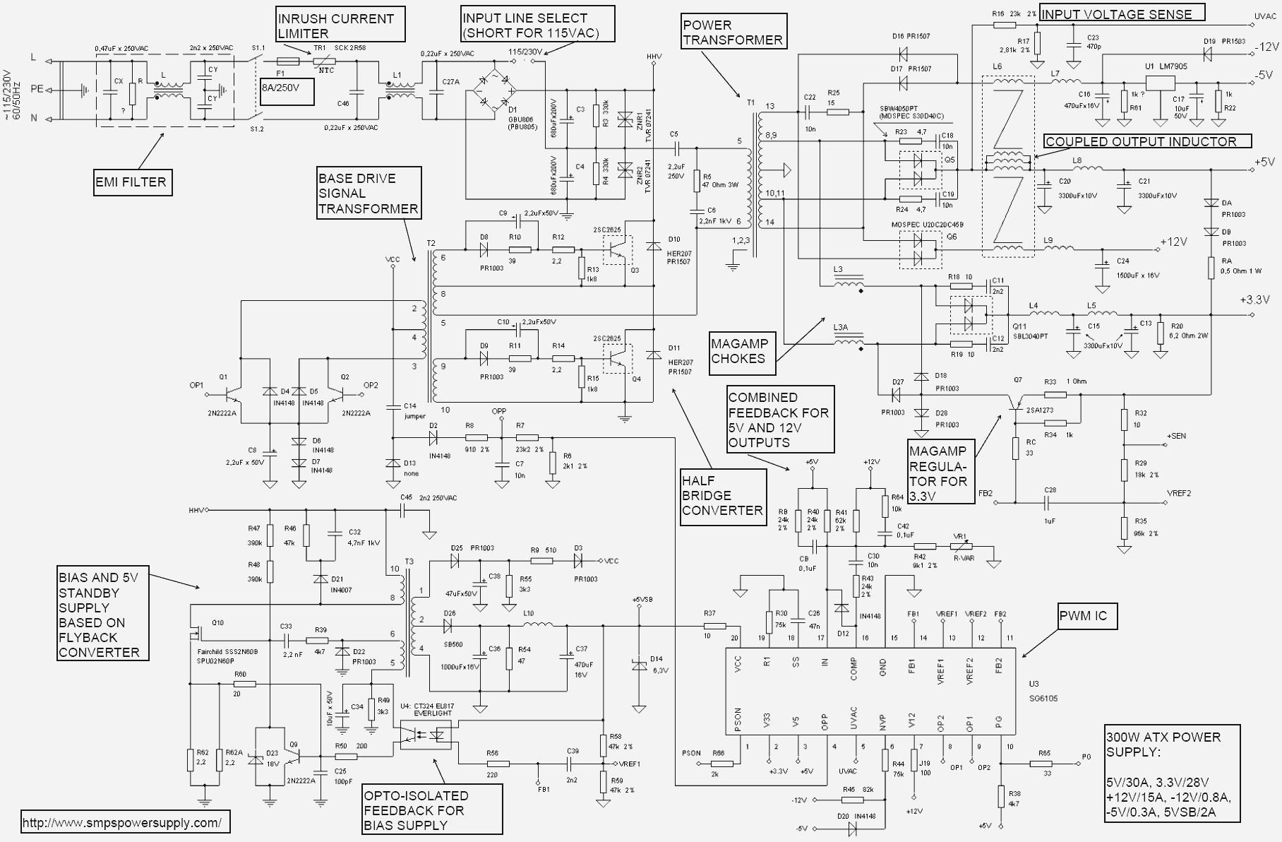
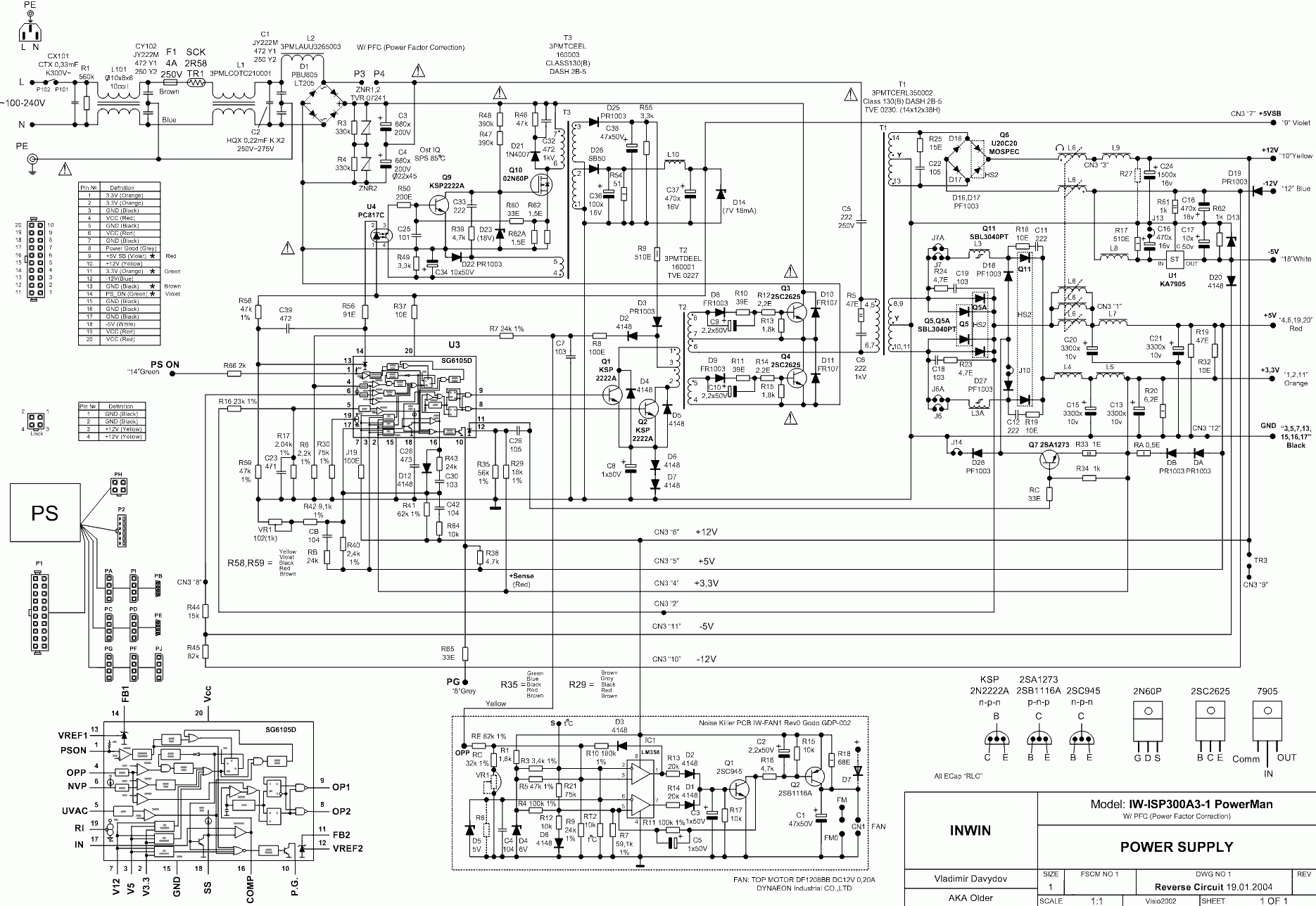
[1] Computers usually get most of their power from switching power supplies for efficiency, but linear regulators still have their place. OlderATXpowersuppliesused the 7805 for the 5V standby power, while othersusedthe related 7905 and 7912 regulators for -5V and -12V. Modern computers still use linear regulators in surprising numbers. For instance the MacBook Pro (A1278) uses a low-dropout regulator to generate 1.8 volts, a switching controller with 3.3 and 5V linear regulators inside, a main switching controller with a 5V regulator inside, a low-noise 4.6V regulator for audio and another regulator to generate 3.3V for the keyboard.
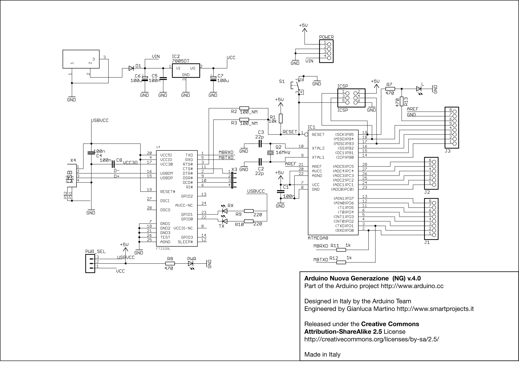
[2] Earlier Arduinos such as the Arduino USB, NG and Severino were powered through a 7805 regulator. Recent Arduino models, however, use a switching step-down converter and an ultra-low-dropout 3.3V regulator. This regulator uses the same principles as the 7805, but is much more advanced.
[3] A big advantage of more modern voltage regulators is they don't require as large an input voltage. The 7805 requires at least two extra volts input (i.e. 7 volts in to produce 5 volts out) - this is the dropout voltage. Newer low-dropout (LDO) regulators can require as little as 0.1 extra volts. Modern regulators (such as the TPS796xx) also have much less noise in the output. Despite this, the 7805 is still popular, especially withhobbyists. Adafruit has a nice comparison of regulators.
[4] Depending on the application, you'd probably want to add input and output capacitors to the 7805 regulator to filter out transients due to fluctuations in the input voltage or output load.
[5] While the 7805 chip has a single layer of metal over the silicon to interconnect the circuitry, modern CPUs use many more layers of metal due to their complexity. For example, Haswell uses 11 layers while IBM's POWER8 uses an astounding 15 metal layers. Needless to say, I'm not going to figure out how those chips work with my microscope.
[6] The 7805 uses a wide variety of transistor layouts, as you can see from the labeled die photo. Several transistors in the bandgap use two emitters for one transistor (e.g. Q2, Q3, Q4, Q5) to improve matching between transistors; the PNP current mirror transistors Q11 and Q11-1 also have multiple emitters. Pairs of transistors can share a single base (e.g. Q11 and Q11-1), share a single collector (Q17 and Q18), or share both (Q14 and Q19). Some transistors move the base to the middle (e.g. Q6). To support high current, the output transistors (Q15, Q16) have a totally different, much larger structure.
[7] You might have wondered why there is a distinction between the collector and emitter of a transistor, when the simple picture of a transistor is totally symmetrical. As you can see from the die photo, the collector and emitter are very different in a real transistor. In addition to the very large size difference, the silicon doping is different. The result is a transistor will have poor gain if the collector and emitter are swapped.
[8] The resistance of a resistor in silicon is proportional to its length divided by its width. If you double the length, it's like two resistors in series, so the resistance doubles. If you double the width, it's like two resistors in parallel, so the resistance is cut in half. One convenient consequence is if the chip is scaled down (Moore's law), the resistors keep the same values, since the width and length scale equally.
Silicon resistance is measured with the unusual unit ohms per square (Ω/□). Note that there's no distance unit - it doesn't matter if you have a square millimeter or square inch of material; the resistance is the same because the dimensions cancel out. For the 7805, I estimate 140 ohms/square for the resistors.
[9] I looked at dozens of datasheets and the chip I examined almost exactly matches the schematic for the Korean Electronics KIA7805. The National LM340/LM78XX schematic is very similar
[10] Bandgap circuits usually have two stable voltages - the desired voltage and 0 volts. To keep the bandgap from getting stuck at 0 volts, a startup circuit will "push" the bandgap away from 0 volts so it will settle at the desired voltage. The startup circuit is discussed in Widlar's application note AN-42 for the similar LM109 (page 5).
[11] When building a bandgap reference, what really matters for VBE is the current density through the transistors - the current divided by the area of the emitter. Decreasing the current through the transistor decreases the current density. The second way to decrease current density is to use a larger transistor with a larger emitter. Often five or ten identical transistors in parallel will be combined to form this large transistor to ensure the large transistor and the small transistor are exactly matched.
[12] The VBE line for a bandgap reference is only perfectly straight in theory, so the resulting bandgap voltage will vary slightly with temperature. To increase stability, some more complex bandgap references compensate for second-order effects.
[13] Bandgap reference references: How to make a bandgap voltage reference in one easy lesson by Paul Brokaw, inventor of the Brokaw bandgap reference. A presentation on the bandgap reference is here. The Design of Band-Gap Reference Circuits: Trials and Tribulations by analog chip design legend Bob Pease discusses real-world bandgap designs.
[14] You might wonder how the error output knows what voltage to switch at. For a Darlington pair (Q7/Q8) to be active, the base voltage must go above 2VBE (Wikipedia). The bandgap reference was constructed assuming that at the reference voltage, there will be VBE drops across Q7 and Q8. Thus, it's not a coincidence that Darlington pair Q7/Q8 is right in the active region (2VBE) at the bandgap voltage making the error output very sensitive to any moves away from the reference voltage. If the output voltage rises or falls, the voltage at the base of Q7 rises or falls accordingly, and the transistors greatly amplify this change. Also note that an increase in output voltage causes a decrease in the error output, yielding negative feedback for the whole chip.
[15] By all reports, Robert Widlar was an amazing analog engineer, as well as an alcoholic crazy guy. Widlar invented key analog IC circuits such as the Widlar current source as well as groundbreaking ICs such as the µA702 and µA723. In 1970 he sold his stock options for a million dollars (about 6 million adjusted for inflation) and retired to Mexico at 33. Some entertaining stories about him are here, on Wikipedia, and pictures of his sheep.
[16] Most 7805 datasheets show the same internal schematic. Some chips using the common design are Fairchild 7800 series, Hi-Sincerity H78XX, FCI LM7800, MCC MC7805, Microelectronics ML7800, Motorola MCT7800, uPC7800H, JRC NJM7800, TI uA7800, Signetics uA7800, and ST L7805. Other chips use variants of the common design: AS78XXA, UTC LM78XX, L78L05 and Motorola MC7800.
The LM109-based design of the 7805 that I looked at is very different from the common design and appears to be fairly rare; it is used by National LM340/LM7800 and KEC KIA7805AF. There are a few differences to note between this design and the original National LM109. In order to support multiple output voltages, the 7805 design uses a resistor divider and a different circuit feeding the bandgap reference. This probably also motivated the removal of a couple transistors from the bandgap circuit so its voltage is one VBE drop lower. The startup circuit is also slightly changed.
[17] Widlar's patent on the bandgap reference is 3617859. A later patent with a bandgap reference very similar to the LM109's is 4249122.
[18] A current mirror is a very useful way of connecting transistors so the current through the second transistor matches the current through the first transistor. For more information about current mirrors, you can check Wikipedia or any analog IC book such as chapter 3 of Designing Analog Chips.
[19] Several sources give an explanation of the common 7805 design that is plausible but wrong. The faulty explanation is that Zener D1 provides the reference voltage. It feeds into a comparator built from Q13 and Q10 (or Q6) as a differential pair and Q1, Q7, and Q2 forming a current mirror active load. The most obvious problem with this is Q13, Q6, R1, and R2 are all tied together which would short out the two sides of the supposed differential pair / current mirror.
Ironically, the design of the 7905 (the negative-voltage version of the 7805) is similar to the erroneous 7805 explanation. The 7905 uses a Zener diode to provide the reference voltage. A comparator with a current mirror active load generates the error signal by comparing the reference voltage with the feedback voltage. Meanwhile another current mirror ensures a constant (probably temperature-compensated) current flows through the Zener diode. I had expected the 79XX chips would be mirror-images of the 78XX chips, but the internal design turns out to be fundamentally different. This explains why the block diagrams in 7905 datasheets show a comparator and 7805 datasheets just show an "error amplifier" box.
[20] In the common 7805 design, I believe the purpose of Q7 and R10 is to pull the same current from Q1's base that Q4 and R14 pull from Q2's base, to keep both sides balanced. Because R1 is 1KΩ and R2+R3 is 21kΩ, 21 times the current should flow through Q1 as through Q2.
33 comments:
Great job! I appreciate the circuit description and pictures.
I'm a complete electricity nitwit, but stuff like this is always interesting and even mildly comprehensible. Thanks for this!
Thank's Ken for another enlightening post!
Always appreciate the time and effort that is placed in exploring and explaining the machines that rule our lives - an education indeed.
Fantastic post, Ken. As your footnote says, I'd always assumed the Zener was responsible for the reference voltage in a 78xx part. I'm looking forward to more posts like this one.
This was absolutely amazing! I found it from another site, but have followed you in my blog reader thingie (sorry, not very good with technology).
Can't wait for your next post! I don't suppose you would mind emails, would you?
Your blog is wonderful. Please continue to share your knowledge of electronics and your discoveries regarding consumer devices.
I have used so much of your insight and information which is either nicely written up or beutifully built. Keep it coming.
Great work with the interactive schematic/layout! I've just challenged a colleague by emailing him a link to the bare schematic and asked him to identify the largest transistor in the schematic. (Although I'm pretty sure that he will find it almost immediately...)
Thanks Prof Ken
Graet ! Thank you !
Thanks for another great post, this was a nice read!
After reading I had to read the Bob Pease post you linked to about Widlar, and then I had to end up reading more about Widlar which was pretty fascinating. It's very interesting to think of how these designs were first invented in the early days of IC design and how sometimes a very few people in a field come up with some of the groundbreaking innovations.
When I was a chip designer, the block diagrams and schematics on the datasheet were usually drawn by someone in marketing, and usually without any input from the circuit designers. Perhaps this was to avoid leaking any super-secret IP :-) Reading the datasheet and finding out what was supposed to be in my chips was usually surprising and sometimes quite amusing. I would not read too much into the schematic on a datasheet, in fact many times the schematics have obvious errors that would make them not work. It's a pity that the schematics aren't accurate (with transistor sizes and netlists provided) as this would allow much better spice models. Other IC companies have no trouble reverse engineering the chips in any case.
Thank you for this !
Would be interesting to compare with a guenine ST part, before assuming it is counterfeit.
In 1984 at my first job, the boss decided to "save a few bucks" and ordered some TO-220 7805s from Europe. These things did not work at all. They did pass a voltage but it was not regulated. I remember taking one and cracking it open in a vise to discover there was no chip inside--the Vin and Vout leads were a single stamp of metal making a wire. It turns out these things were from the former USSR via some distributor in Poland. I got the boss to go back to Hamilton-Avnet.
Thanks Prof Ken for the great post. How did you make that interactive chip viewer?
Thanks for the comments. Andreas: you can challenge your colleague to find the second-largest transistor in the die photo. Crow: you win for best counterfeit with the chip that was just a piece of wire inside. Anonymous, I wrote a few details on the interactive chip viewer here. It's a bunch of JavaScript; the hard part was defining the regions for every component in the chip.
Please don't take this as a negative comment, but I was concerned about your comments concerning sawing the tops off metal-can power devices, especially when you 'want to show kids what ICs look like inside'.
Nothing wrong with wanting to do that, but back in the day the advice was to be EXTREMELY careful when sawing open metal-can devices, especially power devices, as they commonly contained beryllium oxides which are toxic on dust inhalation and also carcinogens: see eg http://www.ccohs.ca/oshanswers/diseases/beryllium.html
I don't know about current production but I suspect it's still used; certainly it will be in any 70's/80s/90s production items you miught want to sacrifice.
So please use dangerous material protocols if you must saw open a metal can power device, at the very least using well-fitting masks, latex gloves and good ventilation. Don't let kids play with them! Looking through a scope after they have been cleaned should be OK.
Even after it's been opened some packages shed beryllium dust, in my experience, so they should be bagged and not left around.
Some plastic packages also used beryllium oxide as a heat conducting element, so please be careful!
Otherwise, interesting article. I used to make sensitive opto sensors like this (in the 70's!) when they were otherwise very expensive... a clear epoxy was used to fill the opened can.
Hi,
I'm trying to implement that design, however i dont't know what types of components zener diodes,bjts) are used in second figure (most popular 7805 design). Could you give these components names? Thank you.
Excellent post, I really learn something new from you. thanks for sharing.
I remember that in the late 70s was common to find 7805 marked 2805 but i do not know the story behind. I still have some on circuits in my recycle bin
"2805" on the die is likely a date code: 28th week of 2005.
The best, you got very good semiconductor knowledge.
hope you post more.
i am using this chip from past 1 year and we have developed more then 2000 power supply units and used this as a 5 volt provider. and nowadays when the user(Indian army) started using this chip is failing very frequently.i could not find the root cause. can somebody help me.all the i/p, o/p, are within the specifications.
Thanks for the effort that went into this. Interesting read.
Looking closely at the die, I wonder how can those tiny wires going from and to the casing can withstand 1 amp of DC current ???
Indian army should use indian designs, i.e. Tata motors design, so ur 5V stabs are good enough for indian army:)
I have a KIA78R08API which is believe is a clone of the Fairchild KA78R08C LDO regulator. This regulator has an enable/disable 4th pin. I would be interested in knowing what would cause this pin to pull itself low with a +voltage applied to it.
I know, it's weird but maybe theirs a simple reason.
Thanks and this blog is fantastic!
Probably one of the most interesting articles I've ever read. Thank you very much for this!
I took some pictures of a ST 7824C:
https://www.richis-lab.de/voltageregulator12.htm
The circuit of the 7824C fits to the schematic in the datasheet.
It really looks like ST has put different circuits in the TO3 and the TO220/D2PAK packages (7800 vs. 7800C). That explains why the specifications of the TO3 are different to the T220 and D2PAK.
The very first data sheet for 7805 had the pinout wrong, and I ended up with an "interesting" burn mark on my index finger! We were so excited to see a single-chip regulator, we bought one as soon as it was announced!
I found a dead link ... the text in question reads "Because silicon is so sensitive to impurities, the original silicon wafer must be an insanely pure crystal, up to 99.999999999% pure - a level known as eleven nines. " The Link on "eleven nines" is gone ... you should replace the dead link with this link instead: https://web.archive.org/web/20100312040734/http://cleanroom.byu.edu:80/EW_formation.phtml
A fascinating article, thanks. Not sure if anyone else has pointed out that the reason the 79xx series are not mirror images of the 78 series is that high-current high-gain devices are easier to make in a given silicon area as NPN than PNP. I have some Motorola 7902 regulators which seem pretty rare.
Re cutting the lids of IC and power transistors, I did this back in the 1970s and was fascinated to find some of them lit up when the conducted ...
Post a Comment