Punched card sorters were a key part of data processing from 1890 until the 1970s, used for accounting, inventory, payroll and many other tasks. This article looks inside sorters, showing the fascinating electromechanical and vacuum tube circuits used for data processing in the pre-computer era and beyond.
Herman Hollerith invented punch-card data processing for the 1890 US census.[1] Businesses soon took advantage of punched cards for data processing, using what was called unit record equipment. Each punched card held one data record, consisting of multiple data fields. A card sorter sorted the cards into the desired order. Then a machine called a tabulator read the cards, added up desired fields and printed a report.
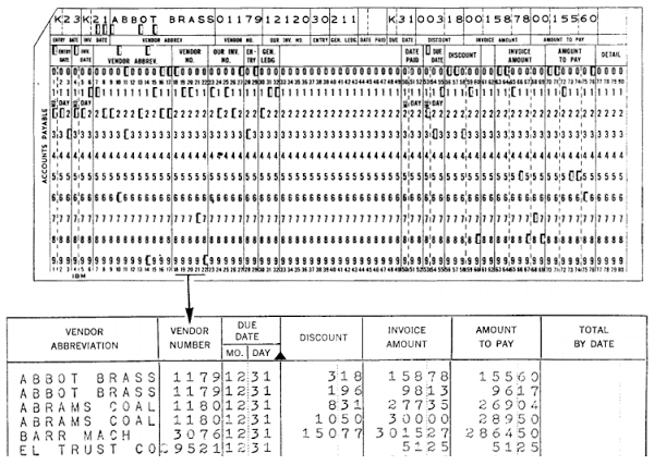
For example, a company could have one card for each invoice it needs to pay, as shown below, with fields for the vendor number, date, amount to pay, and so forth. The card sorter ordered the cards by vendor number. Then the tabulator generated a report by reading each card and printing a line for each card. Mechanical counters in the tabulator summed up the amounts, computing the total amount payable. Many other business tasks such as payroll, inventory and billing used punched cards in a similar manner.
The surprising thing about unit record equipment is that it originally was entirely electro-mechanical, not even using vacuum tubes. This equipment was built from components such as wire brushes to read the holes in punched cards, electro-mechanical relays to control the circuits, and mechanical wheels to add values. Even though these systems were technologically primitive, they revolutionized business data processing and paved the way for electronic business computers such as the IBM 1401.
How a sorter works
A card sorter takes punched cards and sorts them into order based on a field, for example employee number, date, or department. One application is putting records in the desired order when printing out a report.[2] Another application is grouping record by a field, for instance to generate a report of sales by department: the cards are first sorted based on the department field, and then a tabulator sums up the sales field, printing the subtotal for each department.To sort punched cards, they are loaded into the card hopper and fed through the sorter. Cards are read and directed into one of the 13 card pockets: 0 through 9, two "zone" pockets, and a Reject pocket. This is very different from a typical sort algorithm — cards aren't compared with each other — so you may wonder how this machine sorts its input.
Card sorting uses a clever technique called radix sort. The sorter operates on one digit of the field at a time, so to sort on a 3-digit field, cards are run through the sorter three times. First, the sorter deposits the cards into ten bins (0-9) based on the lowest digit of the field. The operator gathers up the cards from the bins in order (0 bin first and 9 bin last) and they are sorted again on the second-lowest digit, again getting stacked in bins 0-9. The important thing is that the cards in each bin will still be ordered from the first pass: bin 0 will have cards ending in 00 first, and cards ending in 09 last. The operator gathers up the cards in order again, yielding a stack that is now sorted according to the last two digits. The cards are run through the sorter a third time, this time sorting on the third-lowest digit. After the last run through the sorter, the cards are in order, sorted on the entire field.
The radix sort process is fast and simple. You may be familiar with comparison-based sorting algorithms like quicksort that compare and shuffle entries, taking O(n log n) time. Radix sort can be implemented with a simple electric mechanism (along with an operator busily moving stacks of cards around), and takes linear time.[3] Although the sorter's hopper can hold 3600 cards, it can sort as many cards as desired, as long as the operator keeps loading and unloading them.
The sorting mechanism
You might expect a sorter to have multiple sensors to read the holes from a card and 10 flippers to direct the card into the right bin. But the actual implementation of the early sorters is amazingly simple and clever, using a single sensor and a single electromagnet.
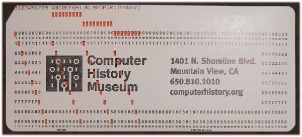
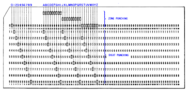
The photo above shows the layout of a standard IBM punched card, which stores 80 characters in 80 columns. The characters are printed along the top of the card and the corresponding holes are punched below. For a digit, each column has a single punch in row 0 through 9 to indicate the digit in that column. (I'll explain the two additional "zone" rows for alphabetic characters later.)
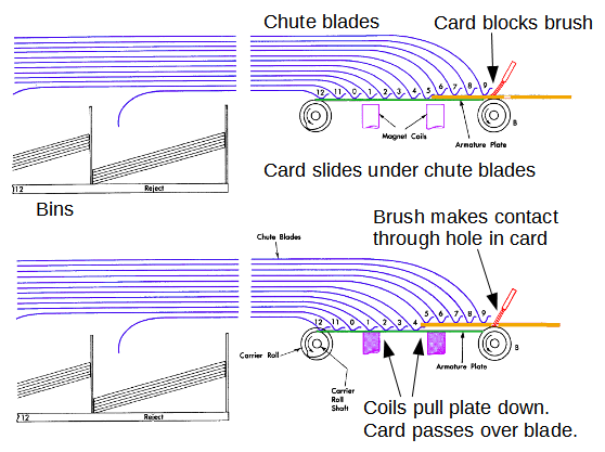
The diagram below shows how the card sorter works. Cards are fed through the sorter "sideways" starting with the bottom edge (called the "9-edge" because the bottom row is row 9). A small wire brush (red) detects the presence or absence of a hole; the brush will contact the rows in order from 9 to 0. An intact card blocks the wire brush from contacting the metal roller. But if there is a hole in the card, the brush makes contact with the roller through the hole, completing an electrical circuit.
A stack of metal guides (called chute blades) is used to direct the card into the appropriate bin. As a card is fed through the sorter mechanism, it slides under the chute blades as shown in the top illustration. If the brush (red) makes contact through a hole, it trips an electromagnet (purple) that pulls down a metal armature plate (green), allowing the ends of the chute blades to drop down. This causes the card to go above the chute blade rather than underneath it. The key is the chute blades have the same spacing as the rows on the card so the hole is detected just before the card reaches the corresponding blade. (If no hole is detected, the card passes under all the chute blades and into the Reject bin.)
For example, in the diagram above the card has slid under chute blades 9 through 5. The brush makes contact through hole 4, energizing the electromagnet and causing the blades to drop just before the card reaches blade 4. Thus, the card is directed into chute 4.
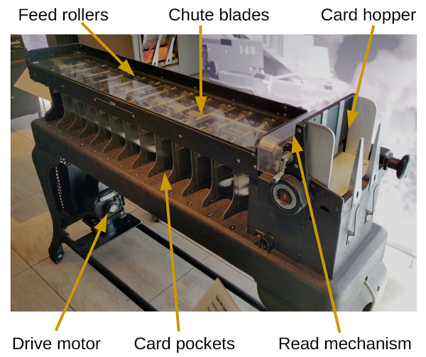
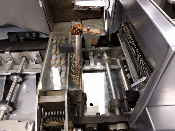
The chute blades can be seen in the photo below; they are the metal strips running down the center of the sorter between the feed rollers. Each chute blade ends at the appropriate pocket, causing the card to drop into the right location.
Alphabetic sorting
Numeric values have one hole in a column and are straightforward to sort, but how about alphabetic characters? In addition to the ten numeric rows 0-9, punched cards also have two additional "zone" rows (11 and 12). The diagram below shows the encoding; a letter combines a digit punch (1-9) with a zone punch (a hole in 0, 11 or 12). Confusingly, row 0 is used both as a zone and a digit.
With this encoding, a sorter can perform an alphabetical sort in two passes. The first pass sorts on the numeric rows, putting cards into bins 1 through 9. These bins are gathered up in order and the cards are sorted a second time. For the second sort, the zone rows (0, 11 and 12) are read and the digit rows are ignored. The result is A through I sorted in bin 12, J through R in bin 11, and S through Z in bin 0. For multiple-character fields, the process is repeated for each column.
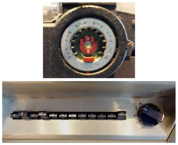
Control switches on the sorter select a numeric or zone sort. The photos below show these controls on the Type 80 (top) and 83 (bottom) sorters. The Type 80 sorter has a round commutator with tabs that are moved in or out to select which rows to use; the red tab selects a zone sort. The Type 83 sorter has pushbuttons to select rows, as well as a switch to select different types of sorting (Numeric, Zone, or Alpha).
A brief history of IBM's horizontal sorters
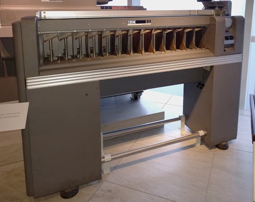
Type 80 sorter
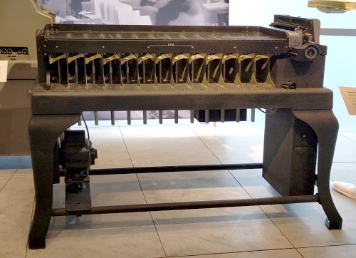
In 1925, IBM introduced its first horizontal card sorter, the Type 80.[4] This sorter became very popular with 10,200 units in use by 1943. IBM continued to support this card sorter until 1980, a remarkable lifespan of 55 years.
The Type 80 sorter performed useful data processing with electromechanical technology without the benefits of transistors or even vacuum tubes. The Type 80 sorter used a relay to latch the electromagnet on for the duration of the card; this is the extent of its "intelligence".[5]
Even though it was electrically simple, the sorter was a piece of precision machinery. It sorted 450 cards per minute, so the chute blades must pop down and up more than 7 times per second. Any timing error could result in a mis-sorted card or could cause the blade to nick the edge of the card.
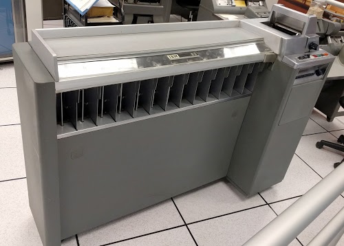
Type 82 sorter
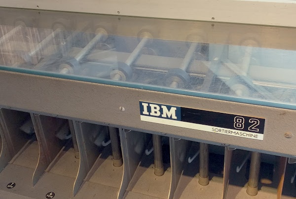
IBM's next sorter model was the Type 82, able to sort 650 cards per minute, and renting for 55 dollars per month. At the faster speed, an electromechanical relay wasn't fast enough to control the magnet, so vacuum tubes were used.
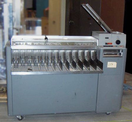
Type 83 sorter
The next sorter model, the Type 83, was introduced in 1955. It could sort 1000 cards per minute and rented for 110 dollars per month. This sorter used a much more advanced technique for processing cards: instead of selecting the card chute at the instant a hole was detected, the 83 sorter read all the holes in the column before selecting a card chute. This allowed the Type 83 sorter to perform tasks that were impossible with the previous sorters, such as rejecting erroneous cards that had multiple holes in one column.
Type 84 sorter
IBM's most advanced sorter was the Type 84, introduced in 1959 and produced until 1978. This sorter replaced the wire brush with a photoelectric sensor and used solid state technology. A vacuum feed grabbed cards more effectively. With these improvements, it could process 2000 cards per minute, over 30 cards per second flying through the sorter.
Sorters and IBM's industrial design
As you may have noticed from the photos above, IBM's industrial design changed drastically from the early sorters.[6] The Type 80 sorter is an example of IBM's early hardware, built of cast iron in a "Queen Anne" style with curved cabriole legs. The mechanisms and motor of the Type 80 sorter are visible. By the time of the Type 82 sorter, IBM was using industrial design firms and had an "understated Art Deco aesthetic". Note the curved, sleek enclosure of the Type 82 sorter, and its shiny horizontal metal trim. The Type 83 and Type 84 sorters are more boxy, without the decorative trim, moving closer to the dramatic modernist style of IBM's computers of the 1960s.The technology inside the sorter
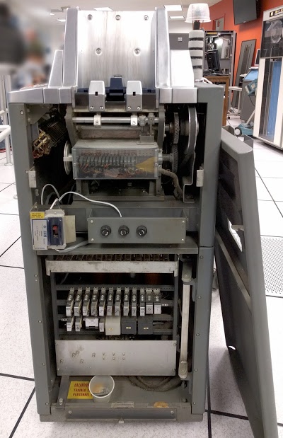
This section looks inside the Type 83 sorter and describes how it was implemented using tube and relay technology. Unlike earlier sorters, the Type 83 sorter read the entire column before selecting the bin for the card. This permitted more complex processing, such as detecting erroneous cards with multiple punches. The sorter used 12 vacuum tubes to store the holes in the column as they were read. Electromechanical relays implemented the decision logic to select the bin, and then solenoids activated the chute blade for that bin.Removing the panel from the end of the sorter shows most of the mechanism (below). At the top is the feed hopper where cards are fed into the sorter. On the right, a pulley connects the feed mechanism to the motor. Mechanical cams (behind clear plastic) are also driven by the motor. Below the power switch and fuses, the 12 vacuum tubes are barely visible. Two rows of rectangular relays provide the control logic for the sorter. Behind the relay panel is the power supply for the sorter.
There is no clock for the sorter; all timing is relative to the position of the driveshaft, with one 360° rotation corresponding to one clock cycle. Sixteen cams (behind plastic near the top of the sorter) open and close switches at various points in the cycle to provide electrical signals at the right times.
The photo below shows the brush and the chute blade selection solenoids. On the right, you can see the pointer that indicates the selected column. The brush itself is below the pointer. In the middle are the 12 oblong coils that select the bin. These coils push the selected chute blades down (using the levers at the front), allowing the card to pass between the selected blades.
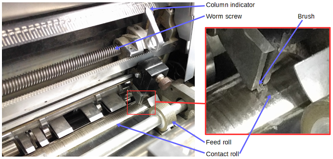
The card is read by a brush that makes electrical contact through a hole in the card. The brush is positioned to the proper column by manually turning a knob that rotates the worm screw and moves the brush. As you can see in the photo below, the small brush contacts the metal contact roll.
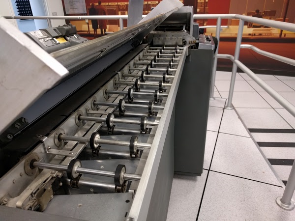
The photo below shows the drive rollers that feed cards through the sorter, dropping them into the appropriate bins, as directed by the chute blades. The chute blades are barely visible; they are the inch-wide metal strip on the right. The chute blades are stacked together, with just enough room for a card to pass between them.
In order to read a column before selecting a chute, the sorter needed a storage mechanism to remember the 12 hole values. This mechanism is an interesting combination of mechanical switches, vacuum tubes and relays.
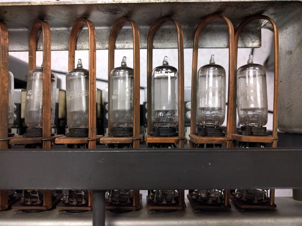
Each bit of storage used a 2D21 thyratron tube. This interesting tube is about 2 inches tall. Unlike a regular vacuum tube, it contains low-pressure xenon. If the tube is activated (via its two control grids), the xenon ionizes, causing the tube to remain on until current through it is interrupted. Thus, the tube can be used for storage. Each tube is in a pull-out module that has the necessary resistors at the bottom.
As each card row passes under the brush, the corresponding thyratron is selected. Rotating cams attached to the driveshaft mechanically activate switches at the right point in the cycle to select each thyratron.[7] It seems strange to combine high-speed tubes with mechanically operated switches, but cam-based timing was common in that era. Once the column has been read into the thyratron tubes, the hole pattern is transferred to relays for "processing".
Relay logic
Unlike the older sorters, the Type 83 sorter reads the entire column before selecting a bin. This lets it, for instance, reject erroneous cards with multiple punches in one column. How does it detect multiple punches? Instead of using logic gates built from tubes or transistors, it uses a network of relays. This section describes how relay logic works.
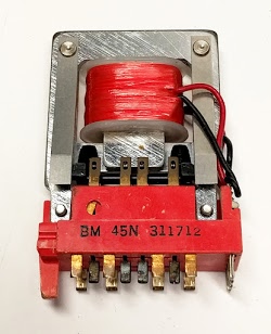
A relay (shown above) contains an electromagnet coil that moves contacts, switching circuits on or off like a toggle switch. In a typical relay, the circuit connects to the "normally closed" pin when the relay is inactive, and connects to the "normally opened" pin when the relay is active. A relay may have multiple sets of these contacts. The diagram below shows how a relay appears on IBM schematics. On the left is the electromagnet coil, and on the right is one set of contacts. The diagram shows the inactive state, with the center wire touching the bottom contact. When the relay is energized, the center wire moves and touches the top contact, switching the circuit.[8]
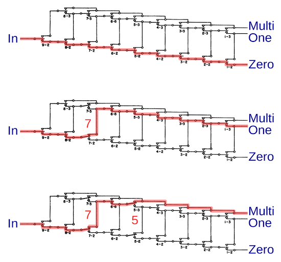
The diagram below shows the relay circuit in the sorter that counts the holes and determines if zero, one, or more holes are present. With no holes (top), current flows along the bottom path. A single hole (middle) energizes a relay (#7 in this case), transferring current to the middle path. The next hole (bottom) energizes a second relay (#5 in this case), transferring current to the top path. Thus, this chain of relays determines the number of holes present, and erroneous cards can be rejected.
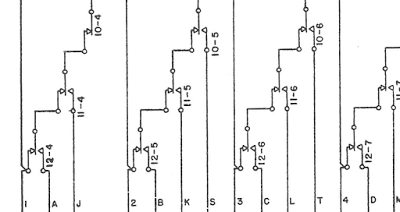
A more complex relay circuit was the optional faster alphabetic sorting feature available on the Type 83 sorter. For an additional $15 a month rental fee, customers could sort the most common letters in one pass, saving time while sorting. This circuit used several large relays, each with a dozen sets of contacts (an unusually large number). These relays decoded the hole pattern to determine the specific character and then selected the appropriate bin. The diagram below shows a small part of the circuit.
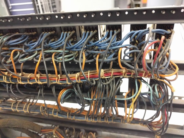
The photo below shows the wiring on the back of the relay panel. The wiring in the sorter is all point-to-point wiring, rather than printed circuit boards. Note that the wires are carefully laced into neat bundles.
The power supply
When the Type 80 sorter was introduced, standard AC power hadn't fully taken over and parts of the United States used DC or 25 Hertz AC.[9] Thus, the sorter needed to handle fifteen different line inputs including unusual ones such as 115V DC or 230V 25 Hertz AC. Internally, the sorter circuits used 115V DC, a rather high voltage for "logic" circuits. If the line voltage was AC, the power supply used a transformer and selenium rectifiers (an early form of diode build from stacks of selenium disks) to produce DC. The Type 81 power supply was considerably more complicated since its vacuum tubes required -40V DC. To create this voltage, the power supply used a vacuum tube oscillator, another transformer and vacuum tube diodes.
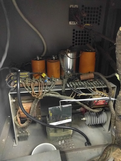
By the time the Type 83 sorter was introduced, AC line power was almost universal, so a transformer could replace the oscillator power supply. The picture above shows the power supply in a Type 83 sorter, showing the large power transformer (left), capacitors (orange cylinders), and selenium rectifiers (gray finned objects at lower left and right). Needless to say, modern switching power supplies are much more compact and efficient than the early power supplies used in the sorters.
Conclusion
The Computer History Museum in Mountain View demonstrates a working card sorter weekly, so stop by if you're in the area. Thanks to the IBM 1401 restoration team and the Computer History Museum for access to the sorters.
If you're interested in vintage computing, you should follow me on Twitter.
Notes and references
[1] Herman Hollerith is one of the key inventors of the data processing industry. He founded a company that, after various mergers, became IBM in 1924. Hollerith's 1889 patent 395,782 (Art of Compiling Statistics) describes how to record data on punched cards and then generate statistics from those cards. Hollerith also gave his name to the Hollerith constants used for character data in old FORTRAN programs.
[2]
Using a sorter to order cards for a report is
roughly analogous to a
database ORDER BY operation.
Sorting cards so subtotals can be computed is analogous to
a GROUP BY operation.
[3] Strictly speaking, radix sort on n records takes O(m*n) time if the field is m characters wide. But since punched cards limit m to 80 columns, m can be considered a constant factor, making radix sort linear.
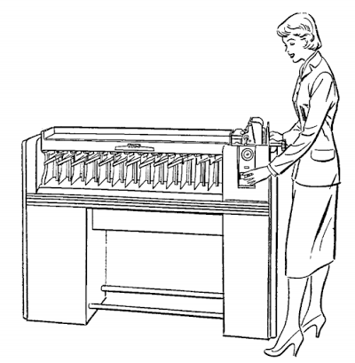
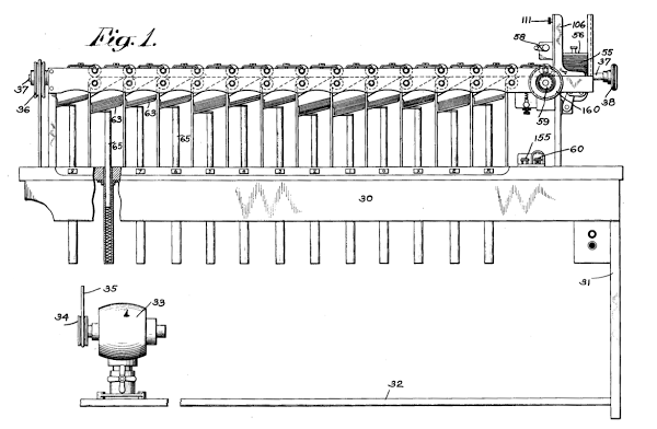
[4] The Type 80 card sorter was invented by Eugene Ford in 1925 and received patent 1,684,389 (Card feeding and handling device). The card sorter has many interesting features so it's a bit surprising that the patent covers just the "picker" that feeds cards through the sorter one at a time. The drawing below is from the patent, and can be compared with the photo of the sorter.
You might wonder how the Type 80 card sorter was introduced in 1925 when the modern punched card was developed a few years later in 1928. The first Type 80 sorters worked with 45-column cards and were slightly modified in 1928 to support 80-column cards. The changes were minor since the cards remained the same size; the brush mechanism needed to have 80 stops instead of 45.
[5] For detailed information on the sorters (including wiring diagrams) see the Reference Manual and the IBM Customer Engineering Manual.
[6] The industrial design section is based on The Interface: IBM and the Transformation of Corporate Design. This book gives a detailed history and analysis of IBM's industrial design.
[7] A primitive but complex mechanism is used to select one thyratron tube as each row is read. Although the 12 thyratrons are physically installed in a line, they are electrically wired in a 3x4 grid. Four mechanical cams select a grid row; one cam is activated at a time. You'd expect three cams to select a grid column, but there are six. The problem is a single mechanical cam can't turn the switch on and off fast enough. The solution is to use two cams in series with staggered operation. The first cam closes the circuit to select the thyratron, while the second cam opens a short time later to de-select the thyratron. By using two cams and two switches, each switch has more time to open and close. As a card is read, the cams open and close, selecting each thyratron in sequence to hold the value (hole or no hole) for that card position. After the card column has been read into the thyratrons, the hole pattern is transferred to 12 relays and the thyratrons are reset for the next card.
[8] IBM's relays are discussed in detail in Commutation and Control, IBM Relays Reference Manual and IBM Relays Customer Engineering.
[9] The story of why parts of the US used 25 Hertz power instead of the standard 60 Hertz is interesting. Hydroelectric power was developed at Niagara Falls starting in 1886. To transmit power to Buffalo, Edison advocated DC, while Westinghouse pushed for polyphase AC. The plan in 1891 was to use DC for local distribution and (incredibly) compressed air to transmit power 20 miles to Buffalo, NY. By 1893, the power company decided to use AC, but used 25 Hertz due to the mechanical design of the turbines and various compromises. In 1919, more than two thirds of power generation in New York was 25 Hertz and it wasn't until as late as 1952 that Buffalo used more 60 Hertz power than 25 Hertz power. The last 25 Hertz generator at Niagara Falls was shut down in 2006. See 25-Hz at Niagara Falls, IEEE Power and Energy Magazine, Jan/Feb 2008 for details.
