Control your mouse with an IR remote

You can use an IR remote to control your computer's keyboard and mouse by using my Arduino IR remote library and a small microcontroller board called the Teensy. By pushing the buttons on your IR remote, you can steer the cursor around the screen, click on things, and enter digits. The key is the Teensy can simulate a USB keyboard and mouse, and provide input to your computer.

How to do this

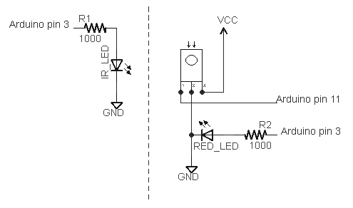
I built a simple sketch that uses the remote from my DVD player to move and click the mouse, enter digits, or page up or down. Follow these steps:
  • The hardware is nearly trivial. Connect a IR detector to the Teensy: detector pin 1 to Teensy input 11, detector pin 2 to ground, and detector pin 3 to +5 volts.
  • Install the latest version of my IR remote library, which has support for the Teensy.
  • Download the IRusb sketch.
  • In the Arduino IDE, select Tools > Board: Teensy 2.0 and select Tools > USB Type: Keyboard and Mouse.
  • Modify the sketch to match the codes from your remote. Look at the serial console as you push the buttons on your remote, and modify the sketch accordingly. (This is explained in more detail below.)
To reiterate, this sketch won't work on a standard Arduino; you need to use a Teensy.

How the sketch works

The software is straightforward because the Teensy has USB support built in. First, the IR library is initialized to receive IR codes on pin 11:
#include <IRremote.h>

int RECV_PIN = 11;
IRrecv irrecv(RECV_PIN);
decode_results results;

void setup()
{
  irrecv.enableIRIn(); // Start the receiver
  Serial.begin(9600);
}
Next, the decode method is called to receive IR codes. If the hex value for the received code corresponds to a desired button, a USB mouse or keyboard command is sent. If a code is not recognized, it is printed on the serial port. Finally, after receiving a code, the resume method is called to resume receiving IR codes.
int step = 1;
void loop() {
  if (irrecv.decode(&results)) {
    switch (results.value) {
    case 0x9eb92: // Sony up
      Mouse.move(0, -step); // up
      break;
    case 0x5eb92:  // Sony down
      Mouse.move(0, step); // down
      break;
...
    case 0x90b92:  // Sony 0
      Keyboard.print("0");
      break;
...
    default:
      Serial.print("Received 0x");
      Serial.println(results.value, HEX);
      break;
    }
    irrecv.resume(); // Resume decoding (necessary!)
  }
}
You may wonder where the codes such as 0x9eb92 come from. These values are for my Sony DVD remote, so chances are they won't work for your remote. To get the values for your remote, look at the serial console as you press the desired buttons. As long as you have a supported remote type (NEC, Sony, RC5/6), you'll get the hex values to put into the sketch. Simply copy the hex values into the sketch, and perform the desired action.

There are a few details to note. If your remote uses the RC5 or RC6 format, there are actually two different codes assigned to each button, and the remote alternates between them. Push the button twice to see if you'll need to use two different codes. If you want to send a non-ASCII keyboard code, such as Page Down, you'll need to use a slightly more complex set of commands (documentation). For example, the following code sends a Page UP if it receives a RC5 Volume Up from the remote. Note that there are two codes for volume up, and note that KEY_PAGE_UP is sent, followed by 0 (no key).

    case 0x10: // RC5 vol up
    case 0x810:
      Keyboard.set_key1(KEY_PAGE_UP);
      Keyboard.send_now();
      Keyboard.set_key1(0);
      Keyboard.send_now();
      break;

Improvements

My first implementation of the sketch as described above was very easy, but there were a couple displeasing things. The first problem was the mouse movement was either very slow (with a small step size) or too jerky (with a large step size). Second, if you press a number on the remote, the keyboard input rapidly repeats because the IR remote repeatedly sends the IR code, so you end up with "111111" when you just wanted "1".

The solution to the mouse movement is to implement acceleration - as you hold the button down, the mouse moves faster. This was straightforward to implement. The sketch checks if the button code was received within 200ms of the previous code. If so, the sketch speeds up the mouse movement by increasing the step size. Otherwise it resets the step size to 1. The result is that tapping the button gives you fine control by moving the mouse a little bit, while holding the button down lets you zip across the screen:

    if (millis() - lastTime > GAP) {
      step = 1;
    } 
    else if (step > 20) {
      step += 1;
    }
Similarly, to prevent the keyboard action from repeating, we only output keypresses if the press is more then 200ms after the previous. This results in a single keyboard action no matter how long a button is pressed down. The same thing is done to prevent multiple mouse clicks.
 if (millis() - lastTime > GAP) {
        switch (results.value) {
        case 0xd0b92:
          Mouse.click();
          break;
        case 0x90b92:
          Keyboard.print("0");
          break;
...

Now you can control your PC from across the room by using your remote. Thanks to Paul Stoffregen of PJRC for porting my IR remote library to the Teensy and sending me a Teensy for testing.

IRremote library now runs on the Teensy, Arduino Mega, and Sanguino

Thanks to Paul Stoffregen of PJRC, my Arduino IR remote library now runs on a bunch of different platforms, including the Teensy, Arduino Mega, and Sanguino. Paul has details here, along with documentation on the library that I admit is better than mine.

I used my new IRremote test setup to verify that the library works fine on the Teensy. I haven't tested my library on the other platforms because I don't have the hardware so let me know if you have success or run into problems.

Download

The latest version of the IRremote library with the multi-platform improvements is on GitHub. To download and install the library:
  • Download the IRremote library zip file from GitHub.
  • Unzip the download
  • Move/rename the shirriff-Arduino-IRremote-nnnn directory to arduino-000nn/libraries/IRremote.

Thanks again to Paul for adding this major improvement to my library and sending me a Teensy to test it out. You can see from the picture that the Teensy provides functionality similar to the Arduino in a much smaller package that is also breadboard-compatible; I give it a thumbs-up.

Testing the Arduino IR remote library

I wrote an IR remote library for the Arduino (details) that has turned out to be popular. I want to make sure I don't break things as I improve the library, so I've created a test suite that uses a pair of Arduinos: one sends data and the other receives data. The receiver verifies the data, providing an end-to-end test that the library is working properly.

Overview of the test

The first Arudino repeatedly sends a bunch of IR codes to the second Arduino. The second Arduino verifies that the received code is what is expected. If all is well, the second Arduino flashes the LED for each successful code. If there is an error, the second Arudino's LED illuminates for 5 seconds. The test cycle repeats forever. Debugging information is output to the second Arduino's serial port, which is helpful for tracking down the cause of errors.

Hardware setup

The test hardware is pretty simple: one Arduino transmits, and one Arduino receives. An IR LED is connected to pin 3 of the first Arduino to send the IR code. An IR detector is connected to pin 11 of the second Arduino to receive the IR code. A LED is connected to pin 3 of the second Arduino to provide the test status.
schematic of test setup

Details of the test software

One interesting feature of this test is the same sketch runs on the sending Arduino and the receiving Arduino. The test looks for an input on pin 11 to decide if it is the receiver:
void setup()
{
  Serial.begin(9600);
  // Check RECV_PIN to decide if we're RECEIVER or SENDER
  if (digitalRead(RECV_PIN) == HIGH) {
    mode = RECEIVER;
    irrecv.enableIRIn();
    pinMode(LED_PIN, OUTPUT);
    digitalWrite(LED_PIN, LOW);
    Serial.println("Receiver mode");
  } 
  else {
    mode = SENDER;
    Serial.println("Sender mode");
  }
}
Another interesting feature is the test suite is expressed very simply:
  test("SONY4", SONY, 0x12345, 20);
  test("SONY5", SONY, 0x00000, 20);
  test("SONY6", SONY, 0xfffff, 20);
  test("NEC1", NEC, 0x12345678, 32);
  test("NEC2", NEC, 0x00000000, 32);
  test("NEC3", NEC, 0xffffffff, 32);
...
Each test call has a debugging string, the type of code to send/receive, the value to send/receive, and the number of bits.

On the sender, the testmethod sends the code, while on the receiver, the method verifies that the proper code is received. The SENDER code calls the appropriate send method based on the type, and then delays before the next test. The RECEIVER code waits for a code. If it's correct, it flashes the LED. Otherwise, it sets the state to ERROR.

void test(char *label, int type, unsigned long value, int bits) {
  if (mode == SENDER) {
    Serial.println(label);
    if (type == NEC) {
      irsend.sendNEC(value, bits);
    } 
    else if (type == SONY) {
...
    }
    delay(200);
  } 
  else if (mode == RECEIVER) {
    irrecv.resume(); // Receive the next value
    unsigned long max_time = millis() + 30000;
    // Wait for decode or timeout
    while (!irrecv.decode(&results)) {
      if (millis() > max_time) {
        mode = ERROR; // timeout
        return;
      }
    }
    if (type == results.decode_type && value == results.value && bits == results.bits) {
      // flash LED
    } 
    else {
      mode = ERROR;
    }
  }
}
The trickiest part of the code is synchronizing the sender and the receiver. This happens in loop(). The receiver waits for 1 second without any transmission, while the sender pauses for 2 seconds after each time through the tests. Thus, the receiver will wait while the sender is running through tests, and then will start listening just before the sender starts the next cycle of tests. One other thing to point out is if there is an error, the receiver will skip through all the remaining tests, light the LED to indicate the error, and then will wait to sync up again. This avoids the problem of one bad test getting the receiver permanently out of sync; the receiver is able to re-sync and continue successfully after a failed test.
void loop() {
  if (mode == SENDER) {
    delay(2000);  // Delay for more than gap to give receiver a better chance to sync.
  } 
  else if (mode == RECEIVER) {
    waitForGap(1000);
  } 
  else if (mode == ERROR) {
    // Light up for 5 seconds for error
    mode = RECEIVER;  // Try again
    return;
  }
The test also includes some raw mode tests. These are a bit more complicated, since I want to test the various combinations of sending and receiving in raw mode.

Download and running

I'm gradually moving my development to GitHub at https://github.com/shirriff/Arduino-IRremote.

The code fragments above have been slightly abbreviated; the full code for the test sketch is here.

To download the library and try out the two-Arduino test:

  • Download the IRremote library zip file.
  • Unzip the download
  • Move/rename the shirriff-Arduino-IRremote-nnnn directory to arduino-000nn/libraries/IRremote. The test sketch is in examples/IRtest2.

To run the test, install the sketch on two Arduinos. The test should automatically start running. Note that it is a bit tricky to use two Arduinos at once. They will probably get assigned different serial ports, and you can switch ports using the Tools menu. If you get confused, you can plug one Arduino in at a time, and then you can be sure about which one is getting installed.

My plan is to do more development on the library, now that I have a reasonably solid test suite and I can be more confident that I don't break things. Let me know if there are specific features you'd like.

Thanks go to SparkFun for giving me the second Arduino that made this test possible.

Improved Arduino TV-B-Gone

Oct 2016: An updated version of the code is on github, thanks to Gabriel Staples.

The TV-B-Gone is a tiny infrared remote that can turn off almost any TV. A while ago, I ported the TV-B-Gone software to the Arduino; for details on the port and how it works see my previous post on the Arduino TV-B-Gone.

Mitch Altman, the inventor of the TV-B-Gone, made some improvements to the code for a weekly TV-B-Gone constructing workshop in San Francisco at Noisebridge. If you're in the San Francisco area and are interested in the TV-B-Gone, you might want to check it out.

The main bug fix in the new version is the European codes will now work (if you ground pin 5). (The problem was a bunch of #ifdefs to fit the codes into the ATtiny's limited memory; taking out the #ifdefs fixed the problems.) Pressing the trigger button during transmission will now restart the codes. The delay between codes was increased, which should make transmission more reliable. The Arduino's processor will now sleep when not transmitting (thanks to ka1kjz). (Unfortunately, the rest of the Arduino components are still draining power, so sleep mode will be more useful with stripped-down Arduino variants.)

Important: the pins have been changed around in the new version (to avoid conflicts with the serial port). Pin 2 is now the trigger switch, Pin 3 is the IR output, and Pin 5 is grounded if you want European codes. If you built an Arduino TV-B-Gone before and want to use the new code, make sure you connect to the right pins.

Here's Mitch Altman's schematic for the Arduino TV-B-Gone (click for larger): Arduino TV-B-Gone schematic

To build the Arduino TV-B-Gone, follow the above schematic and download the sketch from github. My previous post on the Arduino TV-B-Gone has more information on wiring it up, if you need it.