Inside a RFID race timing chip: die photos of the Monza R6

I recently watched a cross-country running race that used a digital timing system, so I investigated how the RFID timing chip works. Each runner wears a race bib like the one below. The bib has two RFID tags, consisting of a metal foil antenna connected to a tiny RFID (radio-frequency identification) chip. At the finish line, runners pass over a pad that reads the chip and records the finish time. (I'm not sure why there are two RFID tags on each bib; perhaps for reliability of detection.)

This race bib has two RFID chips and antennas for timing the race. The RFID chips are tiny black specks in the small loop of each antenna.

This race bib has two RFID chips and antennas for timing the race. The RFID chips are tiny black specks in the small loop of each antenna.

The die photo below shows the RFID chip used on these tags. To create it, I took 22 photos of the chip with my metallurgical microscope and stitched them together to create a high resolution photo. (Click the image for a larger version.) To prepare the chip, I removed it from the plastic carrier with Goof Off, dissolved the antenna with pool acid (HCl), and burnt off the mounting adhesive over a stove. This process left the chip visible with just a bit of debris that wouldn't come off. I'd probably get better results with boiling sulfuric acid, but that's too hazardous for me. I described the image stitching process in this article.

Die photo of the Impinj Monza R6 RFID chip.

Die photo of the Impinj Monza R6 RFID chip.

The chip turns out to be the Monza R6 RFID chip built by Impinj, a leading RFID chip company. The chip datasheet includes a die photo of the chip (below), but it is mostly obscured for some reason. Even so, it is clear that the chip in the datasheet matches the one I photographed.

Die photo of the Monza R6 RFID chip from the datasheet. Most of the chip is obscured; the antenna contacts are visible at the top.

Die photo of the Monza R6 RFID chip from the datasheet. Most of the chip is obscured; the antenna contacts are visible at the top.

How RFID timing works

The basic idea of RFID timing is the finish line has an RFID reader connected to a directional antenna. When the runner crosses the finish line, the reader communicates with the RFID chip on the runner's tag, determines the runner's ID number, and records the elapsed time.

You might expect that the RFID chip simply returns the runner's number as the runner crosses the finish line, but there's a complex two-way protocol at work here. The chip uses the industry-standard EPC standard, and supports about a dozen commands: Select, Query, Read, Write, Lock, and various others. (While some RFID chips include cryptography, the R6 does not.) The chip receives commands from the reader and responds according to the protocol. The chip's memory includes an Electronic Product Code (EPC), which is a 96-bit universal identifier. In this case, the EPC value is returned to identify the runner.

One interesting thing is the RFID chip has no power source other than the radio signal; it is passive and doesn't need a battery. The reader transmits a radio signal (between 860 and 960 MHz), which is picked up by the antenna on the tag. The tiny amount of power received by the tag is what powers the RFID chip.

To send data to the RFID chip, the reader pulses the radio signal it emits. The chip detects these pulses and converts them into bits, using various modulation schemes (details). You might expect the chip transmits a radio signal to send data back to the reader, but it doesn't have enough power to do that. Instead, the chip dynamically changes load on the antenna (basically a transistor shorts out the antenna) while the reader is sending the radio signal. This causes a tiny change in the signal strength at the reader (about 1 part in 1000), which the reader can detect. This process, called backscatter, allows the chip to send data back to the reader without using power.

You might wonder how the system works if two runners cross the finish line at the same time—how do both tags get read without interference? RFID tags are designed for inventory systems, so they are designed to handle environments where there are hundreds of tags in range of the reader. They use an efficient anti-collision protocol. The reader can minimize collisions by querying a subset of tags at a time ("I only want to hear from tags whose ids start with 123.") By rapidly iterating through subsets, a large number of tags can be queried with minimal conflicts. Collisions are handled using a protocol called the Q-algorithm. Essentially, each tag waits a random amount before responding, so hopefully there won't be a collision. If there is a collision, tags wait a longer random amount next time until they can respond without collisions. This is based on the ALOHA protocol, which was also used to handle collisions on Ethernet networks.

Inside the chip

Below is another die photo. I took this one earlier in the cleaning process, so there is more debris on the chip surface. The colors are slightly different in this photo due to different microscope camera settings.

Die photo of the Monza R6 RFID chip.

Die photo of the Monza R6 RFID chip.

Because the chip is complex and has multiple layers of metal, I was unable to analyze its circuitry in detail. However, I can make some informed speculation about it. The top part of the chip is the analog circuitry, extracting power from the antenna, reading the transmitted signal, and modulating the return signal. The two antenna contacts are the large gold pads at the top (on the left and right). The rectangles between the antenna contacts are probably transistors and capacitors forming a charge pump to extract power from the radio signal (see patent). The voltage received from the radio signal is about 200 millivolts, while the chip's circuitry requires about 1 volt. The charge pump boosts the incoming voltage to the higher voltage required.

The middle of the chip has the logic circuitry. Given the complex protocol that the chip handles, you might expect a microprocessor to control the chip. But it uses a complex state machine instead, presumably to keep the chip small and reduce power consumption. This is probably build from CMOS standard digital logic cells, connected by the visible wiring (horizontal lines). This logic includes a pseudo-random number generator to support the anti-collision algorithm.

The chip has the label "IMPINJ KELSO". It's unclear why it is labeled "KELSO" and not "R6". I couldn't find any references to a "kelso" chip, so this could be an internal name. The Impinj company is in Seattle, Washington and Kelso is a small city in Washington, so perhaps that's the connection.

The bottom third of the chip likely contains the storage. The black rectangles above and below the IMPINJ KELSO text are probably the 12 bytes of non-volatile memory (NVM) that hold the tag identification. (This is essentially flash memory.) This Impinj patent discusses the NVM system. Writing the memory requires about 12 volts, which is provided by another charge pump. The gold squares scattered across the chip are probably test points used to program the chip and verify proper operation during manufacturing.

These chips are really small

Let me emphasize how tiny the RFID chips are—they are specks, about the size of a grain of salt. According to the datasheet, the chip is 464.1µm x 400µm (about 1/64 inch on a side). This is much smaller than a typical IC, and explains why the RFID chip doesn't break if the tag is flexed. The biggest problem I had with the die photos was making sure I didn't lose the chip. If I brushed against the chip it could stick to my finger and vanish until I carefully searched my hands to find it. The image below shows the Monza 4, a similar but slightly larger RFID chip, on top of a penny, next to a grain of salt. (A couple months ago, I wrote about the Monza 4 chip and how it is times the Bay to Breakers race.)

The RFID chip used to identify runners is very small, about the size of one of the letters on a penny. A grain of salt (next to R) and the RFID chip (next to U).

The RFID chip used to identify runners is very small, about the size of one of the letters on a penny. A grain of salt (next to R) and the RFID chip (on top of U). This chip has four antenna contacts.

The antenna

Closeup of the RFID antenna and chip. The chip is the black speck in the center above DogBone, below the + sign. The two halves of the antenna are seemingly shorted together, but that's an important part of the RF impedance matching.

Closeup of the RFID antenna and chip. The chip is the black speck in the center above DogBone, below the + sign. The two halves of the antenna are seemingly shorted together, but that's an important part of the RF impedance matching.

The antenna seems straightforward at first—two metal strips connected to the chip. But if you look more closely, you'll notice that the strips are joined together above the chip, which would short out the signal. How does this work? The short answer is it's RF magic. The longer answer is the antenna is carefully designed to match impedance between the transmitter and the chip, so as much power as possible is received by the chip. The central part of the antenna is the "loop" and the two long parts of the antenna are the "dipole". The loop doesn't short out the dipole, but instead they work together. The area of the loop acts as an antenna, and the dipole provides the appropriate impedance so the system resonates at the right frequency. The "dogbone" antenna shape isn't artistic but helps fit a longer dipole into the available area. RFID antennas are explained in more detail in this application note. The tag (combining the antenna and chip) is produced by Smartrac (whose name is barely visible under the black text), and sells for about 13 cents.

The RFID system is similar in some ways to the NFC (near-field communication) that smart phones use for tap-and-pay. The following infographic summarizes the differences (full size).

RFID vs. NFC: What's the difference?

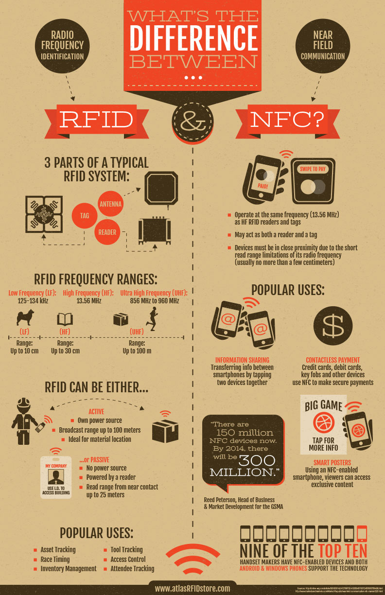
This infographic is courtesy of atlasRFIDstore.

Conclusion

The RFID chips used for race timing are very small but include a lot more complexity than you'd expect. I took some die photos of the Monza R6 chip that show the analog and digital circuitry crammed into a piece of silicon the size of a grain of salt. The chip manages to power itself off the radio signal, allowing it to operate without a battery. This circuitry supports a complex communication protocol between the RFID tag and the reader. The foil antenna is carefully designed to maximize power transfer to the chip. All this is combined into a tag that sells for under 13 cents.

I announce my latest blog posts on Twitter, so follow me at kenshirriff.

Simulating a Xerox Alto with the ContrAlto simulator: games and Smalltalk

The revolutionary Xerox Alto computer came out in 1973 and set the direction for personal computing. If you want to try out the Alto's software, the easiest approach is the ContrAlto simulator. This article describes how to set up the ContrAlto simulator, explains where to find Alto disk images, and shows some of the programs you can run on it.

If you're just joining this series, the Alto was designed at Xerox PARC in 1973 to investigate personal computing. It introduced the GUI, Ethernet, high-quality computer typography and laser printers to the world, among other things. The Alto was used to build Smalltalk, which was one of the first object-oriented programming languages and had a huge influence on modern programming languages. Y Combinator received an Alto from computer visionary Alan Kay, who led the Smalltalk research at PARC. I'm helping restore the system, along with Marc Verdiell, Carl Claunch Luca Severini, Ed Thelen, and Ron Crane. The ContrAlto simulator (developed by Josh Dersch at the Living Computer Museum in Seattle) has been very helpful in our restoration—we can debug by comparing our real system to the simulator. If you're in the Seattle area, you can see a couple running Altos at this museum.

Using ContrAlto

ContrAlto is written in C# and only works on Windows. To install ContrAlto, download the zip file. Open the zip file and click on ContraltoSetup.msi to run the standard installer.

Next, you'll need a Xerox Alto disk image. The real Alto uses 14" removable disk packs that hold 2.5 megabytes, as shown in the photo below. A disk pack is loaded into the Alto, the system boots off the disk, and then disks can be swapped as necessary. The simulator replaces this process by loading a disk image file into the simulator. There are several archived disk images that you can use. One source is bitsavers.org. Download an image file, such as allgames.dsk.

Inserting a disk into the Xerox Alto's disk drive. The Alto's video display is visible at the back.

Inserting a disk into the Xerox Alto's disk drive. The Alto's video display is visible at the back.

Next, run ContrAlto and tell it to load the disk image: select "System -> Drive 0 -> Load". Select allgames.dsk. Then start the simulator with: "System -> Start" (or Reset if its already running). (Also see the README file.) After a few seconds, the ContrAlto simulator should start up and show you the Alto boot screen and command line prompt.

At the > prompt, hit ? to see the list of files on the disk. Files ending with .~ or .RUN are programs you can execute (by typing the file name). Note that the simulator takes control of your mouse. To release the mouse cursor, press Alt. Click the mouse inside the window to give focus back to the Alto simulation. The easiest way to stop a program is to hit Alt and then select System -> Reset.

Typing a question mark at the Xerox Alto executive prompt displays the contents of the disk.

Typing a question mark at the Xerox Alto executive prompt displays the contents of the disk. The "File / System / Help" menu items are for the ContrAlto simulator, not part of the Alto GUI.

One of the games on the disk is Space Invaders, which can be run by simply typing "invaders". The game is controlled by using the three mouse buttons for left, shoot, and right. This game illustrates the bitmapped graphics of the Alto, an unusual feature for that era due to the high price of memory.

The Xerox Alto has a space invaders game, controlled by the mouse buttons.

The Xerox Alto has a space invaders game, controlled by the mouse buttons.

Star Trek was clearly popular with the Alto programmers. The allgames disk lets you battle Klingons with the Spacewar game (below). It also includes Trek, one of the first networked multiplayer games, which took advantage of the system's Ethernet.

The Spacewar game on the (simulated) Xerox Alto lets you battle Klingons.

The Spacewar game on the (simulated) Xerox Alto lets you battle Klingons.

Smalltalk

Smalltalk is a highly-influential programming language and environment that introduced the term "object-oriented programming" and was the ancestor of modern object-oriented languages. Smalltalk was developed on the Xerox Alto by Alan Kay, Dan Ingalls, Adele Goldberg and others. The Alto's Smalltalk environment is also notable for its creation of the graphical user interface with the desktop metaphor, icons, scrollbars, overlapping windows, popup menus and so forth. When Steve Jobs famously visited Xerox PARC, the Smalltalk GUI inspired him on how the Lisa and Macintosh should work; the details of the visit are highly controversial but the description in Dealers of Lightning seems most accurate.

To start up Smalltalk, download st80.dsk. Load the disk image into ContrAlto, reset, and then run "resume small.boot". (A second Smalltalk disk is xmsmall.zip; "resume xmsmall.boot" starts Smalltalk from this disk.). I should mention that the Smalltalk system is fairly slow, so be patient.

Smalltalk-80 running on the Xerox Alto simulator. The large window is the class browser.

Smalltalk-80 running on the Xerox Alto simulator. The large window is the class browser.

The Smalltalk environment includes a class browser window (center) that lets you explore all the classes in Smalltalk. Reflection, being able to examine all the structures of a running system, was a key feature of Smalltalk.

Programming in Smalltalk is too complex to explain here, so I'll just give a simple example of executing an expression. In the upper-left window, type 355.0/113.0 followed by the cursor down key. (Cursor down simulates the Alto's line feed (LF) key, which ends a command. Return will not work.) While this looks like a simple expression, it is object-oriented. The message "/113.0" is sent to the Float object "355.0" (a subclass of Number), executing the division method. (See this document for more information on Alto Smalltalk.)

Smalltalk also includes an image editor called BitRect. To start it, enter "BitRect new fromuser; edit" (and then cursor down) into the upper-left window, and select the size of the editor window with rubber-banding. The editor includes various tools, brush sizes and gray levels. Note that the drawing window can overlap other windows.

Using the BitRect class in Smalltalk to draw an image.

Using the BitRect class in Smalltalk to draw an image. The workspace window in the upper right has useful Smalltalk commands to select and execute.

Writing BCPL code

You can use the simulator to write code in the BCPL language. (BCPL was the precursor to C and is essentially C with a different syntax and no data types.) For the BCPL environment, download and uncompress the tdisk4.dsk.Z image. Code is edited using Bravo, the first WYSIWYG document editor. One consequence of using this editor is that code on the Alto can have all the formatting and styling of a document: a variety of proportionally-spaced fonts, bolding, italics, and so forth. (Being able to style code is a nice feature that can make code easier to understand, so the modern approach of writing programs with plain unformatted text seems like a step backwards.) The image below shows some BCPL code with formatting applied; the styling has no effect on the code's operation. I wrote an article earlier explaining how to use the Bravo editor and the BCPL compiler, so see that article for details on writing BCPL programs.

The Bravo editor provides WYSIWYG formatting of text.

The Bravo editor provides WYSIWYG formatting of text. This BCPL program prints "Hello World", using the Ws (Write String) function.

The diagnostics disk

If you want to follow along with our Alto restoration, we're currently using a copy of the diagnostic disk diags.zip. (You'll need to unzip the disk image before loading it.) This disk includes the keyboard test, MADTEST microcode test, CRT test and other diagnostics we have used in our blog posts and videos.

The ContrAlto debugger

The ContrAlto simulator includes an extensive debugger that lets you examine the running state of the (simulated) Alto. This feature was very helpful for us when debugging the real Alto, since we could compare what was supposed to happen with what was really happening. If you want to see what the Alto does internally, or how microcode interprets machine instructions, give the debugger a try. You'll find that it takes many micro-instructions to execute one machine instruction, and many machine instructions to do anything useful.

To start the debugger, select "System -> Show debugger". This opens up a debugger window, as seen below. The left panel shows the source code for Alto's microcode. The upper center panel shows disassembled machine instructions (using the Nova instruction set). Clicking "Step" will single-step through the microcode. Clicking "Nova Step" will step through Nova code. Click "Run" to return to normal execution

Debug window for the ContrAlto simulator. The left pane shows the microcode. The upper center pane shows the Nova program instructions that are running.

Debug window for the ContrAlto simulator. The left pane shows the microcode. The upper center pane shows the Nova program instructions that are running.

Conclusion

If you don't have a Xerox Alto available, the ContrAlto simulator is the best way to get the Alto experience. I should emphasize that I didn't write ContrAlto; I'm just a user. Josh Dersch at the Living Computer Museum wrote it. The museum also has a couple running Altos, so stop by the museum if you're in Seattle.

For updates on the Alto restoration, follow me on Twitter at kenshirriff.

Restoring YC's Xerox Alto day 10: New boards, running programs, mouse problems

Last week our vintage Alto was crashing; we traced the problem to an incompatibility between two of the processor boards. Today we replaced these boards and now we can run all the programs on the disk without crashes. Unfortunately our mouse still doesn't work, which limits what we can do on this GUI-based computer. We discovered that the mouse has the wrong connector; even though it plugs in fine, it doesn't make any electrical connection.

If you're just joining, the Alto was a revolutionary computer designed at Xerox PARC in 1973 to investigate personal computing. It introduced the GUI, Ethernet and laser printers to the world, among other things. Y Combinator received an Alto from computer visionary Alan Kay and I'm helping restore the system, along with Marc Verdiell, Carl Claunch Luca Severini, Ed Thelen, and Ron Crane,

Incompatibility in the Alto's circuit boards

The Xerox Alto was designed before microprocessor chips, so its processor is built from three boards full of TTL chips: the ALU (Arithmetic-Logic Unit) board, the Control board, and the CRAM (Control RAM) board. The Control board and the CRAM board are the ones that we dealt with today. Last week we traced through software execution, microcode, and hardware circuitry to figure out why some programs on the Alto crashed. We discovered that the problem happened when a program attempted to execute microcode stored in the Control RAM. The microcode RAM select circuit malfunctioned due to some wiring added to the back of the Control board (the white wires in the photo below). Why had this wiring been added to the board? And why did it break things? At the end of last episode, we briefly considered ripping out this wiring, but figured we should understand what was going on first.

This is the Xerox Alto control board, one of three boards that make up the CPU. The board has been modified with several white wires.

This is the Xerox Alto control board, one of three boards that make up the CPU. The board has been modified with several white wires which trigger our crashes.

A bit of explanation will help understand what's going on. Like most computers, the Xerox Alto's instruction set is implemented in microcode. The Alto is more flexible than most computers, though, and allows user programs to actually change the instruction set by modifying the microcode, actually changing the instruction set. To achieve this, the Alto stores microcode in a combination of RAM and ROM.[1] The default microcode (used for booting and for standard programs) is stored in 1K of ROM on the Control board. Some programs use custom microcode, which allows them to modify the computer's instruction set for better performance. This microcode is stored in high-speed RAM on the Control RAM (CRAM) board. Our Alto came with a 1K CRAM board, but some programs (such as Smalltalk) required the larger 3K CRAM board.[2] (This microcode RAM is entirely different from the 512 Kbyte RAM used by Alto programs; you didn't need to fit an Alto program into 3K.)

Inconveniently, the 1K and 3K RAM boards have incompatible connections, and the Control board needs to be wired to work with one or the other. We determined that the white-wire modifications on our Control board converted it from working with a 1K RAM board to working with a 3K RAM board.[3] Unfortunately, our Alto had a 1K RAM board so the two boards were incompatible and programs that attempted to use the microcode RAM crashed, as we saw last week. It's a mystery why our Alto had two incompatible board types, but at least we knew why the modifications are there. (Since our Alto also came with the wrong disk interface card and an unbootable hard disk, we wonder what happened to the Alto since it was last used. It clearly wasn't left in a usable state.)

Fortunately Al Kossow of bitsavers came to our rescue and supplied us with some 3K Control RAM boards and the Control boards to go with them. This saved us from needing to rewire the board we had. Al also provided the strange but necessary connector (visible below on the left) that goes between the Control board and the CRAM board. We swapped these boards with our boards and everything worked without crashing! We could now run all the programs on the disk without crashes.

The Alto's Control board is part of the CPU. This board contains 2K words of microcode ROM, as well as control circuitry.

The Alto's Control board is part of the CPU. This board contains 2K words of microcode ROM, as well as control circuitry. Our original board had 1K of ROM (and 8 empty sockets), while this board has the full 2K of ROM. The ROM chips are in the lower left, with labels. The chip labeled SW3K (upside down) is the PROM that selects the hardware configuration. The spare PROM (labeled SW1) is in the upper left. The edge connector on the right plugs into the backplane, while the two connectors on the left are cabled to the CRAM board.

Some Alto software

With the Alto running reliably, we could try out the various programs on the hard disk that had crashed before. Draw, the Alto's mouse-based drawing program, apparently uses microcode for optimizing performance, so last week it immediately dropped into the Swat debugger. With the compatible boards, Draw ran successfully. Unfortunately, since our mouse isn't working, we couldn't actually draw anything, but you can still see the icon-based GUI below. I've tried Draw on the Alto simulator, and despite the icons, it's not exactly intuitive to use.

'Draw' is the Alto's mouse-based drawing program. Clicking an icon on the left selects an operation.

'Draw' is the Alto's mouse-based drawing program. Clicking an icon on the left selects an operation.

We also tried Bravo, the first WYSIWYG (What you see is what you get) text editor. Again, functionality is limited without the mouse. But I could enter text and change the font to a larger, bold font with proportional spacing. Xerox PARC also invented the laser printer and Ethernet, so one could create documents in Bravo and then print them on a networked laser printer. Charles Simonyi, one of the co-authors of Bravo, later created Microsoft Word, so there's a direct connection between the Alto's editor and Word. I've written more about how to use Bravo here.

'Bravo' is the Alto's WYSIWYG text editor. It supports multiple fonts, among other features.

'Bravo' is the Alto's WYSIWYG text editor. It supports multiple fonts, among other features.

The Alto included a GUI file manager called Neptune, allowing files and directories to be manipulated with the mouse. Neptune has an invisible scroll bar to the left of the file list that appears when you mouse-over it; apparently the Alto also invented the scroll bar.

The Alto includes a graphical file system browser.

The Alto includes a graphical file system browser.

A rather complex GUI is in PrePress, a program that converted a spline-based font to a bitmapped font for display or printing. (You can think of this as a forerunner of TrueType fonts.) High-quality fonts were created for the Alto using the FRED font editor. As you would expect from a document company, these fonts included proportional spacing, ligatures such as "ffl" and "fl", and multiple styles and sizes.

'PrePress' is used to convert a spline-based font into a bitmap suitable for display or printing.

'PrePress' is used to convert a spline-based font into a bitmap suitable for display or printing.

Most importantly, we were able to run MADTEST, the Microcoded Alto Diagnostic test, which runs a suite of low-level diagnostics using microcode. This test ran successfully, increasing our confidence that there are no obscure problems in the processor.

If you want to try these Alto programs for yourself, you can use the ContrAlto simulator, built by the Living Computer Museum. This simulator has been very useful to use for learning how the software is supposed to work.

The mouse

The biggest problem remaining at this point is the mouse doesn't work, so we investigated that next. Although the mouse was invented prior to the Alto, the Alto was the first computer to include the mouse as a standard input device. The Alto uses a three-button mouse that plugs into the back of the keyboard.

The three-button optical mouse.

The three-button optical mouse.

Some Altos had a mechanical mouse, while others had an optical mouse. Our Alto came with an optical mouse, but we couldn't get it to work at all. The mouse uses a special mousepad with a specific dotted pattern (which we didn't have), so at first we suspected that was the problem. However, the mouse didn't respond at all when we used a printed copy of the pattern. We also didn't see any light (visible or IR) from the three illumination LEDs on the mouse, so we suspected bigger problems than a missing mousepad.

Underside of the mouse. The sensor (right) consists of three illumination LEDs surrounding the optical sensor.

Underside of the mouse. The sensor (right) consists of three illumination LEDs surrounding the optical sensor.

Opening up the mouse shows the simple circuitry inside, with a single chip controlling it. The chip is rather unusual since it includes a 16-pixel optical sensor, with a light guide that goes from the bottom of the chip to the bottom of the mouse. The pixel-based optical mouse was invented at Xerox PARC in 1980 (and later patented), so this mouse is somewhat more modern than the original Alto (1973). The handwritten markings on the chip suggest this may have been a prototype of some sort.

Inside the optical mouse. In the middle are the three buttons. At top is the IC that contains the optical sensor.

Inside the optical mouse. In the middle are the three buttons. At top is the IC that contains the optical sensor.

When we closely looked at how the mouse was wired up, we discovered the problem. The mouse plugs into a 19-pin socket (DE-19), while the mouse used a 9-pin plug (usually called DB-9, but technically DE-9), so the connectors are entirely incompatible. The DE-19 has three rows of pins: 6/7/6 (with the middle row empty on the Alto), and the DB-9 has two rows of pins (7/6). The bizarre thing is that the mouse plugged into the socket just fine: the connector shells are physically the same size, and the mouse plug's pins went between the Alto socket's connections. So the mouse was plugged in, but not actually connected to anything! It's surprising the connectors could go together without bending any pins. (Several people have suggested sources for a DB-19 connector. Unfortunately the DE-19 (three rows) has a totally different shape from the DB-19 (two rows).)

The Alto's mouse plugs into the 19-pin connector on the keyboard housing (above). Unfortunately our mouse has a 9-pin connector (below).

The Alto's mouse plugs into the 19-pin connector on the keyboard housing (above). Unfortunately our mouse has a 9-pin connector (below).

After some investigation, we learned that the Alto was missing the mouse when it came from Alan Kay. YCombinator picked up a replacement mouse on eBay, but it wasn't compatible with our Alto. We're still trying to figure out if the mouse is an Alto mouse with a nonstandard connector or if it is for a different machine. The Xerox Star used a 2-button mouse, so the mouse isn't from a Star. Tim Curley at Xerox PARC loaned us a compatible Alto mouse, so we'll give that one a try next episode. We're also looking into making an adapter cable, but DE-19 connectors appear to be obsolete and difficult to find.

Conclusion

Last week we discovered that the control board in our Alto was incompatible with the microcode RAM board. Al Kossow loaned us some compatible boards, and with those boards our Alto has been functioning without any crashes or malfunctions. We discovered that our mouse wasn't working because it had the wrong connector—although it plugged into the Alto, it didn't make any electrical connection. Since the mouse is necessary for many Alto programs, we hope to get the mouse working soon.

For updates on the restoration, follow me on Twitter at kenshirriff. Thanks to Al Kossow for helping us out again.

Notes and references

[1] The table below shows the three microcode configurations the Alto supported. Details are in section 8.4 of the Hardware Manual. The desired configuration is selected by inserting a particular PROM in the Control board: SW1, SW2, or SW3K. Each control board has one PROM in use and an unused PROM in the upper left corner; switching PROMs switches the configuration. The Control board has sockets for 2K of ROM; these sockets are left empty for systems with 1K of ROM.

Configuration NameROMRAM
1K1K1K
2K2K1K
3K1K3K

[2] The Alto introduced the 3K RAM board to take advantage of the new 4 kilobit RAM chips, replacing the 1 kilobit chips on the 1K board. Both boards required 32 RAM chips for the 32-bit micro-instructions, showing that back then you needed a lot of chips for not much memory. The microcode required high-speed static memory, so density was worse with microcode than with regular RAM.

[3] The 3K RAM board requires a few additional signals from the Control board, such as the task id. The 1K RAM board grounds one of the lines used for these signals, so using the 3K Control board with the 1K RAM board (as our Alto did) shorts out one of the bank select lines. This causes bank switching to fail and explains the crashes we saw last week. Schematics for the boards are available at bitsavers.

Restoring YC's Xerox Alto day 9: tracing a crash through software and hardware

Last week, after months of restoration, we finally got the vintage Xerox Alto computer to boot (details) and run programs. However, some programs (such as the mouse-based Draw program) crashed so we knew there must still be a hardware problem somewhere in the system. In today's session we traced through the software, microcode and hardware to track down the cause of these crashes.

For background, the Alto was a revolutionary computer designed at Xerox PARC in 1973 to investigate personal computing. It introduced the GUI, Ethernet and laser printers to the world, among other things. Y Combinator received an Alto from computer visionary Alan Kay and I'm helping restore the system, along with Marc Verdiell, Luca Severini, Ron Crane, Carl Claunch and Ed Thelen. The full collection of Alto restoration posts is here.

When the Xerox Alto encounters a problem, it drops into the Swat debugger.

When the Xerox Alto encounters a problem, it drops into the Swat debugger.

To assist with debugging, the Alto includes a debugger called Swat. If a program malfunctions, it drops into the Swat debugger, as seen above. The debugger lets you examine memory and set breakpoints. It is more advanced than I'd expect for 1973, including a feature to disassemble machine instructions from memory and view them with names from the symbol table.

In our case, the debugger showed that when we ran the MADTEST test program, the Alto had jumped to address 2, which triggered the debugger. The first 8 memory locations in the Xerox Alto contain TRAP instructions to catch erroneous jumps to a zero address (or near-zero address) which can happen if a subroutine return address is clobbered. By examining the stack frames, I determined which subroutine had been called when the system crashed. The problem occurred when the program was jumping to microcode that had been loaded into microcode RAM, Since this is an unusual operation, it would explain why most programs ran successfully and only a few crashed.

Microcode

Microcode is a low-level feature of most processors, but I should explain what it means for a program to jump to microcode, since this is a strange feature of the Alto. Computers execute machine code, the simple, low-level instructions that the CPU can understand; on modern computers this may be the x86 instruction set, while the Alto used the Data General Nova instruction set. Most processors, however, don't run machine instructions directly, but have a microcode layer that is invisible to the programmer. While the processor appears to be running machine instructions, it internally executes microcode, a simpler, low-level instruction set that is a better match for the hardware. Each machine instruction may turn into many micro-instructions.

The Xerox Alto uses microcode much more extensively than most computers, with microcode performing tasks such as device control that most computers do in hardware, resulting in a cheaper and more flexible system. (As Alan Kay wrote, "Hardware is just software crystallized early.") On the Alto, programmers have access to the microcode—a user program can load new microcode into special control RAM. This microcode can implement new machine instructions, optimize particular operations (analogous to GPU programming), or obtain low-level control over the system.

The Xerox Alto's CRAM board (Control RAM) stores 1024 microcode instructions. The 32 memory chips in the lower left provide the 1024x32 storage.

The Xerox Alto's CRAM board (Control RAM) stores 1024 microcode instructions. The 32 memory chips in the lower left provide the 1024x32 storage. Foreshadowing: the connector at the lower left connects the CRAM board to the microcode control board.

Our Alto has 1024 words of microcode in ROM (for the standard microcode) and 1024 words in RAM (for software-controlled microcode). The photo above shows the CRAM (control RAM) board that holds the user-modifiable microcode. This board illustrates the incredible improvements in memory density since 1973—this board required 32 memory chips to hold the 1024 32-bit words (4 Kbytes) of microcode.

The Alto's microcode uses a 1K (10-bit) address space. Since Altos can support up to 2K of microcode in ROM and 3K in RAM, bank switching is used to switch between different 1K memory banks. Bank switching is triggered by a special micro-instruction called SWMODE (switch mode).

Getting back to our crash, the MADTEST test program loads special test microcode into the control RAM. Then it executes the JMPRAM machine instruction to switch execution from machine instructions to the microcode in RAM. The microcode that implements JMPRAM performs a SWMODE to switch execution to the RAM microcode bank and the microcode in RAM will execute. When the microcode is done, it is supposed to return execution to the machine code emulator, and execution of the user-level program (MADTEST) will continue. But somehow execution ended up at address 2, causing the program to crash.

To track down a problem with the Xerox Alto's bank switching circuit, we attached many probes to the CPU control board.

To track down a problem with the Xerox Alto's bank switching circuit, we attached many probes to the CPU control board.

We used a logic analyzer to record every micro-instruction and memory access, so we could determine exactly what went wrong. After a few tries, we captured a trace showing what the Alto was executing until it crashed. Over the past week, I've been using the Living Computer Museum's ContrAlto simulator of the Xerox Alto to understand how the Alto's software and microcode work. With this background, I could interpret the logic analyzer output and map it to the MADTEST code and the microcode. Everything proceeded fine until the JMPRAM instruction was executed. Instead of switching to the microcode in RAM, it was still running microcode from the ROM. Since the micro-address was intended for the RAM code, the processor was running essentially random microcode. Through pure luck, this microcode routine completed and returned control to the regular machine code emulator rather than hanging the system. Unfortunately this code didn't load the return address register, resulting in a jump to address 2 and the Swat crash we saw.

To summarize, everything was working fine except instead of switching to the microcode RAM bank, execution stayed in the microcode ROM bank. This was pretty clearly a hardware problem, so we started looking at the bank switch circuit, which consists of multiple integrated circuits.

The bank switch hardware

The Alto was built at the dawn of the microprocessor age, so instead of using a microprocessor chip, it used three boards of TTL chips for the CPU. The control board interprets the microcode, including performing bank switching, so that's where we started our investigation.

Bank switching in the Alto happens when the SWMODE micro-instruction is executed. The destination bank is selected following complex rules that depend on the hardware configuration and the current bank. Rather than implement these rules with a complex hardware circuit, the Alto designers used the short cut of encoding all the logic into a 256x4 PROM chip. (This also has the advantage that a different hardware configuration can be supported simply by replacing the PROM.) The schematic below shows the PROM (left) generating the bank select signals (yellow), which pass through various chips to create the current bank select signals (right), which are fed back into the PROM for the next cycle.

This schematic shows the Xerox Alto's bank switching circuit, allowing microcode to run from ROM or RAM banks.

This schematic shows the Xerox Alto's bank switching circuit, allowing microcode to run from ROM or RAM banks. (Click for larger image.)

We connected logic analyzer probes so we could trace each chip in the bank select circuit. The PROM correctly generated the RAM bank signals when the SWMODE micro-instruction executed, but in the next step its inputs had reverted to the ROM bank for some reason. This showed the PROM worked, so we continued probing through the circuit. Each chip had the proper output until we got to the multiplexer chip that feeds back to the PROM. (This chip, on the right, handles microcode task switching by selecting either the current task's bank, or the new tasks's bank, which is recorded in a RAM chip.) The input signal to the multiplexer pulsed high for the new bank, but the output stayed low, blocking the bank switch signal. The oscilloscope trace below shows the problem: the input signal (bottom trace) is not passed to the output (middle trace).

A multiplexer IC in the Xerox Alto was failing to pass the bank switch signal from its input (bottom trace) to its output (middle trace).

A multiplexer IC in the Xerox Alto was failing to pass the bank switch signal from its input (bottom trace) to its output (middle trace).

We found a bad chip on the disk interface board a few weeks ago, so had we located a second bad chip? We pulled out the suspicious chip (a 74S157 multiplexer) and tested it in a breadboard to prove that it was faulty. Surprisingly, it worked just fine. Perhaps the problem only showed up at high frequency? We swapped it with an identical chip on the board and the crash still happened. Clearly there was nothing wrong with the chip. But its output stayed low when it should go high. Why was this?

We thought this 74S157 multiplexer IC from the Xerox Alto was faulty. However, the chip worked fine when tested in a breadboard.

We thought this 74S157 multiplexer IC from the Xerox Alto was faulty. However, the chip worked fine when tested in a breadboard.

Our next theory was that something was grounding the chip's output signal, forcing the output to remain low. To test this, we disconnected the chip's output pin from the rest of the circuit by bending the pin so it didn't go into the socket, With the output not connected to the circuit, the output went high as expected. (See oscilloscope trace below.) This proved that the chip worked and something else was pulling the signal low. Since the chip's output was connected to the PROM chip, the obvious suspect was the PROM, which might have an input shorted low. We hoped the PROM chip wasn't at fault, since locating a 1970s-era D3601 PROM chip and reprogramming it would be inconvenient. We pulled the PROM chip out of the board and the short to ground remained, demonstrating the PROM chip was not the culprit.

With the multiplexer's output disconnected from the circuit, the input signal (bottom) appears on the output (top) as expected.

With the multiplexer's output disconnected from the circuit, the input signal (bottom) appears on the output (top) as expected.

We removed the control board from the Alto to examine it for short circuits. On the back of the circuit board, we noticed that two white wires were connected to the multiplexer chip that was causing us problems. (Wires are added to printed circuit boards to fix manufacturing problems, support new features, or support new hardware.) These wires went to the connector that was cabled to the CRAM (control RAM) board shown earlier. With the CRAM board disconnected, the short to ground went away. Thus, the cause of our crashes was these two wires that someone had added to the board! Could we simply cut these wires and have the system work correctly? We figured we should understand why the wires were there, rather than randomly ripping them out. Maybe our control board and CRAM board were incompatible? Maybe these wires were to support the Trident disk drive we aren't using? It was the end of the day by this point, so further investigation will wait until next time.

This is the Xerox Alto control board, one of three boards that make up the CPU. The board has been modified with several white wires.

This is the Xerox Alto control board, one of three boards that make up the CPU. The board has been modified with several white wires which trigger our crashes.

Conclusion

After a bunch of software, microcode and hardware debugging we found that the crashes are due to some wires added to one of the circuit boards. These wires messed up microcode bank switching, causing programs that used custom microcode to crash. Fixing this should be straightforward, but we want to understand the motivation behind these wires. On the whole, the processor is working reliably other than this one issue. Once it is fixed, we can run MADTEST (the microcode test program) to stress-test the processor. If there are no more processor issues, we'll move on to getting the mouse working.

For updates on the restoration, follow me on Twitter at kenshirriff. Thanks to the Living Computer Museum for the extender board and the ContrAlto simulator.

How I added 6 characters to Unicode (and you can too)

Edit (June 2018): Unicode 11 is released, containing the half stars. Now the wait for font support...

Star characters (☆★) have long been part of the Unicode standard, which means they can appear as characters in web pages, text, and email. But half-stars were missing, so they required special images or custom fonts. I recently co-wrote a proposal to add half-star characters to Unicode, and it was just accepted. In an upcoming Unicode release, half-stars will be usable like any other text character. In this article, I discuss how I got the half-star characters and two others added to Unicode.

Usage of the four different half-stars to express 3.5 of 5.

Usage of the four different half-stars to express 3.5 of 5.

Unicode is the computer standard that defines the characters that are used by almost every computer—this standard allows different computers to easily display text in almost every language, and with almost every symbol you might need. (Before Unicode, dealing with non-English text on computers was a mess.) But Unicode doesn't include everything. Last June, a comment on Hacker News complained that Unicode lacked the half-star character used in ratings and movie reviews:

Until Unicode has a half-star character, it won't even be able to encode the average newspaper.

I suggested that someone should propose the half-star to Unicode, but quickly realized that "someone" would be me. Since I had successfully proposed two symbols to Unicode earlier, I knew the process necessary to get the half-star added.

A few years ago, a detailed article described how a couple people got power symbols added to Unicode. Adding a new character to Unicode is easier than most people think. You don't need to pay money, be part of a major company or join a committee. All you need to do is write a proposal explaining why the character is needed. If the Unicode Committee agrees, they'll approve your character for addition to Unicode.

In 2015, I started programming the 1960s-era IBM 1401 mainframe at the Computer History Museum. But when I wrote about the IBM 1401 system, I ran into a problem. This computer uses a 6-bit character set (the precursor to EBCDIC) with some strange characters. All these characters appeared in Unicode, with the exception of one: the Group Mark. I was a bit shocked that Unicode, with its 128,172 characters, lacked a character I needed. Having read about the power symbol team's success in adding characters, I figured it would be interesting to see if I could get the group mark character added to Unicode. I wrote a proposal, submitted it to Unicode, and at the next meeting it was approved.

An explanation of the group mark character from an IBM 705 computer manual (1959).

The group mark character, from an IBM 705 computer manual (1959). Since Unicode lacked this character, you couldn't write this text on a modern computer.

A few months later, I learned that the Bitcoin symbol was missing from Unicode. This was a surprising omission, since the Bitcoin symbol is widely used in the real world. The symbol had been rejected before, so I made a more thorough proposal in October 2015 with the enthusiastic support of /r/bitcoin and other Bitcoin groups. The Bitcoin symbol proposal was accepted by the Unicode Committee in November 2015.

The Bitcoin symbol on an IBM punched card.

The Bitcoin symbol on an IBM punched card. Mining Bitcoins on a punched card mainframe isn't practical, but was an interesting experiment.

So when I saw the comment about half-stars on Hacker News, I figured it would be straightforward to get it accepted to Unicode. I wrote a proposal after discussion on HN and on the Unicode mailing list. The Unicode committee considered the proposal in August 2016, but to my surprise they had also received another half star proposal, so they decided to wait on a single proposal. It turned out that Andrew West had also written a proposal for half-stars, and we had both submitted proposals, unaware of the other. So Andrew and I joined forces and made a combined proposal, which was accepted by the committee Sept 30, 2016.

Why did we propose four different half-stars? We included both the outline half-star and solid half-star because both forms are commonly used. (I wasn't sure if the committee would consider these characters distinct enough to include both, but they did.) Right-to-left languages such as Hebrew do their star ratings right-to-left too (which was a bit of a surprise to me), so we included mirrored versions for RTL languages. Thus, the four different half-stars cover the range of uses.

Half-stars in Hebrew are written right-to-left. From Haaretz 2 November 2012, provided by Simon Montagu.

Half-stars in Hebrew are written right-to-left. From Haaretz 2 November 2012, provided by Simon Montagu.

If there's a character that you want to add to Unicode and it meets the requirements, you should submit a proposal, since its a very interesting process and not too difficult. Make sure your character meets the criteria. In particular, you'll need to find a bunch of examples of the character used in text. The Unicode Committee isn't going to add a character just because you think it's cool, so you need examples to prove the character is in use. Creating a font to demonstrate your new character is probably the most challenging part; I used FontForge. The power symbol team has lots of helpful advice on making a successful proposal. I'm also happy to offer advice if you're writing a proposal.

I should mention that emojis have a totally different process, so don't argue that "since the poop emoji exists, my character should too". (The poop emoji 💩 was added for backwards compatibility with Japanese mobile phones.) For emoji, expected popularity of the symbol is a major factor in acceptance. Regular Unicode, on the other hand, isn't concerned with popularity—historical scripts such as Tangut won't get a millionth the usage of a new emoji—but with existing usage in text. (Reading between the lines, I think a lot of the Unicode committee wishes they weren't in the emoji business at all.)

Once a character is accepted, there's still a long road for it to appear in fonts and be usable. A new version of Unicode is released typically every June, so the half stars will probably appear in Unicode 11.0 mid-2018. The Bitcoin community in particular has had to wait patiently since the Bitcoin symbol just missed the cutoff for Unicode 9.0, so it will probably appear in Unicode 10.0, mid-2017. So if you're patient, eventually you'll be able to use the group mark, Bitcoin symbol and half stars in web pages and text just like any other symbol.