We recently restored an Apollo Guidance Computer, the revolutionary computer that helped navigate to the Moon and land on its surface.1 At a time when most computers filled rooms, the Apollo Guidance Computer (AGC) took up just a cubic foot. This blog post discusses the small but complex switching power supplies that helped make the AGC compact enough to fit onboard the spacecraft.
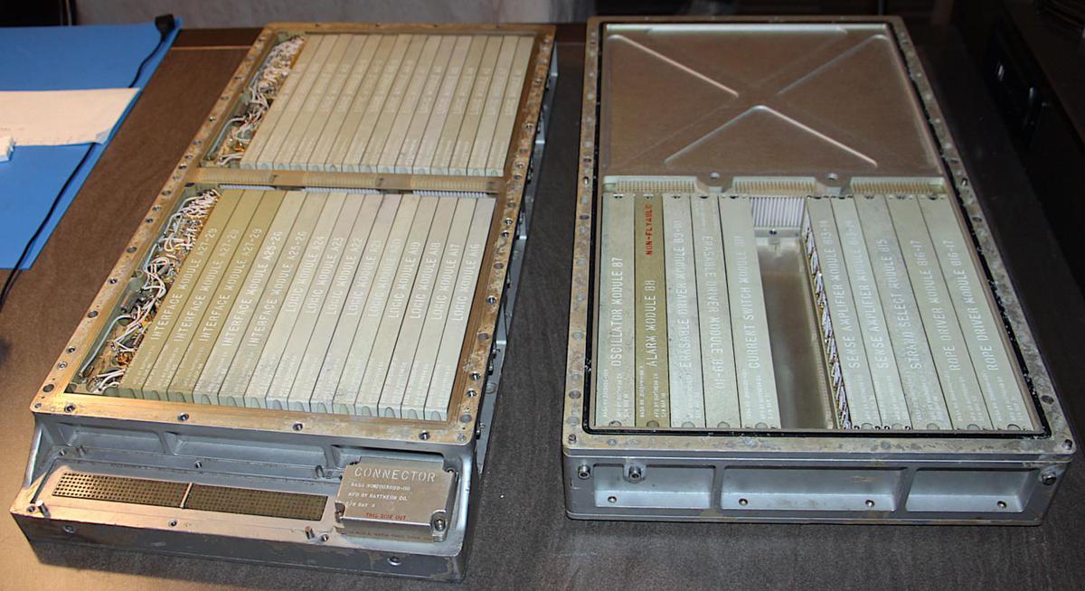
The photo above shows the Apollo Guidance Computer after separating its two trays. Tray A on the left holds the logic and interface modules, while Tray B on the right has the memory circuitry. The AGC has two power supplies in Tray A on the far left: a +4V power supply and a +14V power supply; the power supplies look like a tangle of wires in the photo. The logic circuitry, entirely built from NOR gates, was powered by 4 volts. The interface circuitry and memory used the 14 volt supply.
The spacecraft generated 28 volts from fuel cells, which combined hydrogen and oxygen to produce both water and electricity.3 The task of the power supplies was to convert the spacecraft's 28 volts into the 4 and 14 volts required by the computer.2 The 4-volt power supply could output about 10 amps (i.e. 40 watts) while the 14-volt power supply could output about 5 amps (i.e. 70 watts).4 Thus, the power supplies are roughly equivalent to laptop chargers (although a laptop charger deals with more challenging AC line voltages).
Cordwood construction
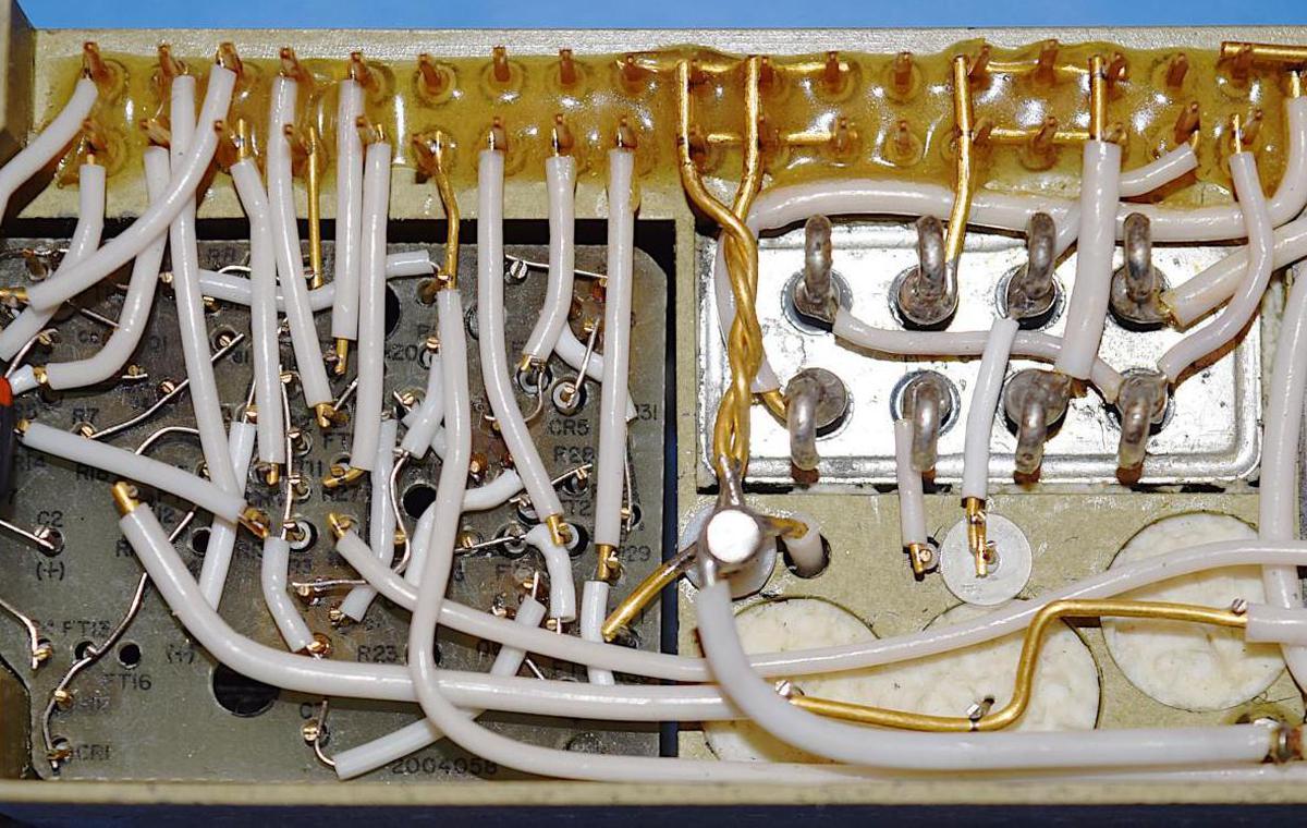
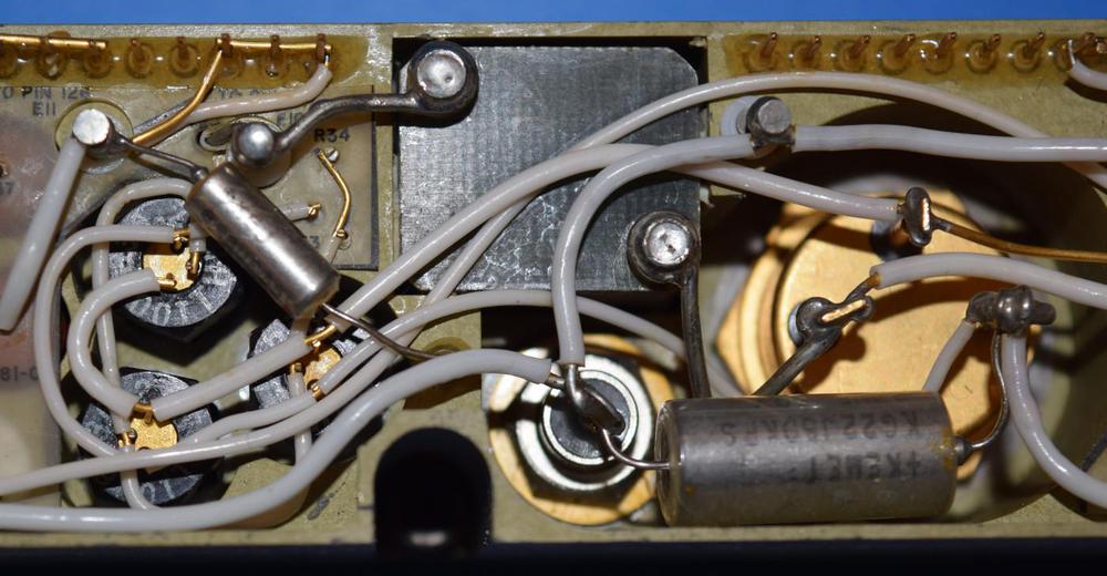
The power supplies, like the AGC's other non-logic modules, were built with cordwood construction. In this high-density technique, cylindrical components were inserted into holes in the module, passing through the module, with their leads exiting on either side.6 The left side of the photo below contains resistors, capacitors, and diodes. Because of the cordwood construction, the components are not visible except for the ends of their leads poking through holes. Point-to-point wiring connected the components with welded connections. (The other side of the module is similar, connecting the other ends of the components.) The shiny rectangle on the right is a relay, used to shut off power for standby operation. The ends of large filter capacitors are visible below the relay.
Cordwood construction was used for high density in applications from aerospace to Cray's CDC 6600 computer. For flight, the AGC's cordwood wiring was encased (potted) in epoxy, protecting it from vibration.
How the power supplies worked
Because the power supplies needed to be lightweight and efficient, they were switching power supplies, an unusual technology for the time. Most computers back then used linear power supplies, which were simpler but much too inefficient for the AGC since excess voltage is turned into waste heat.5 A switching power supply, on the other hand, switches the input voltage on and off at a high frequency. This yields the desired output voltage with very little wasted energy.
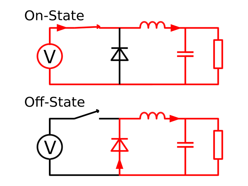
The AGC's power supplies used a common switching circuit called a buck converter, which converts an input voltage to a lower voltage. The diagram below shows the key components: a switch (transistor), inductor, diode, and capacitor. The key idea is that if the switch is closed for more time, more of the input voltage will appear across the load. Thus, the output voltage is controlled by the switch timing. The inductor stores energy and releases it when the switch is open, producing a relatively stable output.
A switching power supply requires a complex control mechanism to switch on and off at the right time. The AGC used a technique called PWM (pulse-width modulation), where power is switched on and off at a fixed frequency (e.g. 20 kilohertz), but changing the fraction of the time the power is on to regulate the voltage.
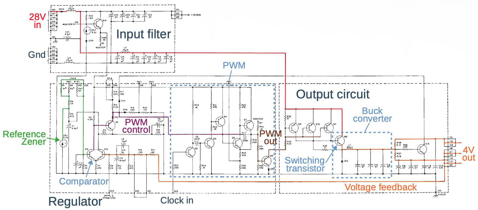
The schematic below shows the AGC's power supply. (Don't worry about reading the details; click for a larger version.) The buck converter itself (outlined in the lower right) has the expected switching transistor, diode, inductor, and capacitors. However, the power supply has many more components to implement the PWM control circuitry.
To summarize the power supply's operation, 28 volts (red) is supplied at the upper left and filtered. The buck converter in the output circuit (right) reduces the voltage to 4 volts (orange) On the control side (left), the output voltage is used for feedback. A two-transistor comparator (lower left) compares the output voltage with a reference voltage (green) set by a Zener diode and resistor network. The output of the comparator (purple) goes through the PWM control circuit where it modifies the width of the pulses (brown) produced by the PWM circuit. These pulses drive the switching transistor in the buck converter, closing the feedback loop. The computer's clock signal providing timing for the PWM circuit.7
The power supply also included a standby circuit. By pressing the STBY key on the display/keyboard (DSKY), a relay would disconnect most of the computer's power. This reduced energy consumption when the computer wasn't needed.8
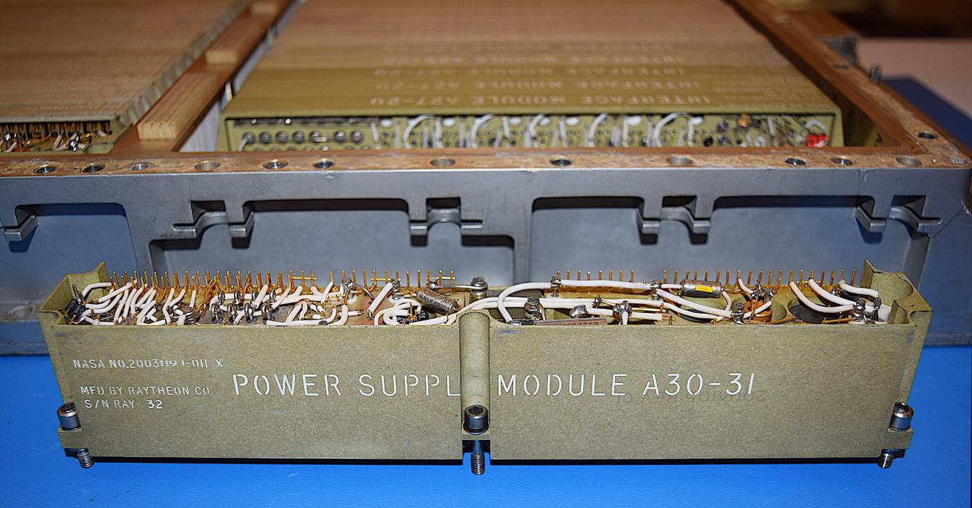
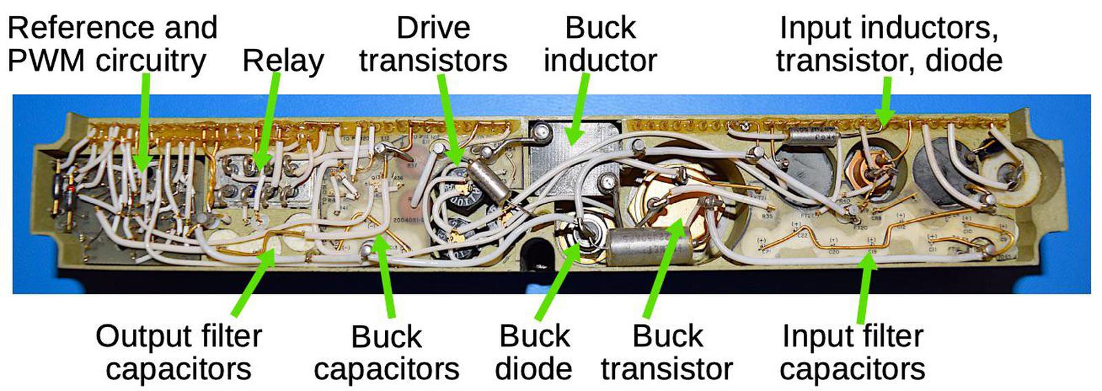
The diagram below shows the top of the power supply module with the major components labeled. Note the large size of the transistors, inductors and filter capacitors compared to the tightly-packed cordwood circuitry on the left. The switching transistor for the buck converter is almost an inch in diameter.
The transistors of the 1960s were barely able to support switching power supplies since they required a power transistor that could operate at both high speed and high current, which was difficult at the time. (Modern transistors (MOSFETs) are cheap and can handle much higher voltages, leading to ubiquitous low-cost phone and laptop chargers that run off an AC outlet.) The switching transistor required a high-current control signal, which was provided by three drive transistors (in a "complementary Darlington" configuration).
Testing the power supply
We extensively tested the AGC's components before powering up the system. For the power supply, we first checked all the tantalum capacitors since tantalum capacitors are prone to shorting out. We found that the capacitors were all in good shape with the proper capacitances. This is in contrast to modern capacitors, which often leak or fail after a few years. NASA used expensive aerospace-grade capacitors and X-rayed each one to test for faults, and this made a large difference.
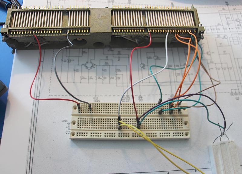
Wiring up each power supply for testing (below) was more complex than you might expect. The AGC used two identical power supplies that supplied 4 or 14 volts. The output voltage was selected by backplane wiring that connected different resistors in the feedback resistor network. We reproduced these connections on a breadboard, as well as connecting up the input and output. Some high-wattage resistors (lower right) served as the load.
We powered-up the AGC modules with 28 volts using a current-limited supply to limit potential damage from any faults. We took measurements and found that 4V power supply produced 4.09 volts while the 14V power supply produced 14.02 volts. The quality of the power was good, with about 30mV of ripple. We were somewhat surprised that both power supplies worked flawlessly after 50 years.
Conclusion
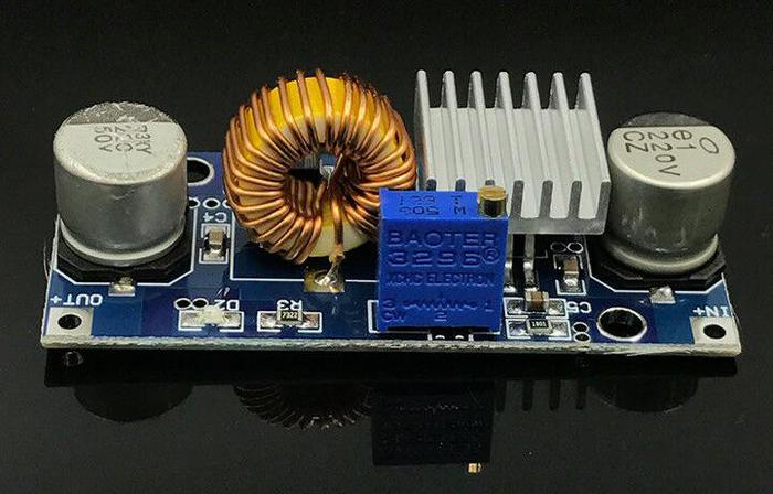
The Apollo Guidance Computer used advanced switching power supplies that were lightweight and efficient. While switching power supplies were exotic in the 1960s, improved semiconductors have made them cheap and ubiquitous. Now the switching transistor, a high-precision voltage reference, and the control logic can be combined on a single chip. The modern equivalent of the AGC's power supply is a tiny 5A buck converter for $1.50 on eBay (below). While I wouldn't trust this converter to get to the moon, let alone still work 50 years from now, it illustrates the dramatic improvements in switching power supply technology. (I've written more about the history of switching power supplies.)
To learn more about our AGC restoration, see Marc's series of AGC videos; the video below shows us testing the power supplies. I announce my latest blog posts on Twitter, so follow me @kenshirriff for future articles. I also have an RSS feed. Thanks to Mike Stewart for photos.
Notes and references
-
The AGC restoration team consists of Mike Stewart (creator of FPGA AGC), Carl Claunch, Marc Verdiell (CuriousMarc on YouTube) and myself. The AGC that we're restoring belongs to a private owner who picked it up at a scrapyard in the 1970s after NASA scrapped it. For simplicity, I refer to the AGC we're restoring as "our AGC". ↩
-
The first version of the Apollo Guidance Computer was known as Block I. The AGC was extensively redesigned to produce the Block II version that was flown. The Block I used +3V and +13V power supplies, while the Block II used +4V and +14V. The Block I power supply is documented here in section 4-8.7. The Block II power supply is documented here in section 4-5.9. ↩
-
The power systems were different between the command/service module and the lunar module. On the command/service module the 28 volts was fed to the different parts of the spacecraft using two buses (Main A and Main B) for redundancy. Main A bus was connected to the A31 power supply module, while the Main B bus was connected to the A30 power supply module (schematic). The two buses were tied together inside the AGC after passing through power rectifiers, so either bus could power the AGC.
(You may recall from Apollo 13: "Houston, we've had a problem. We've had a Main B Bus undervolt". When the oxygen tank exploded, the voltage from the fuel cells dropped, triggering the low voltage alarm.)
The lunar module used batteries for its 28 volt supply, rather than fuel cells. Instead of Main Bus A and Main Bus B, the lunar module had a Commander bus (CDR BUS) and a Lunar Module Pilot bus (LMP BUS). The AGC on the lunar module was only connected to the CDR BUS, so there wasn't redundancy. ↩
-
I estimated the wattage of the power supplies by looking at the current-limit feature. The power supplies have two 0.12Ω current-sense resistors. The voltage drop across these resistors will turn on transistor Q13, which will reduce the PWM output and thus the power supply's output voltage. The 4V power supply has the two resistors in parallel (connected by external wiring). Assuming the transistor turns on at 0.6V, this corresponds to a current of 0.6V / 0.06Ω = 10 A. The 14V power supply uses one current-sense resistor, so it will be limited to around 0.6V / 0.12Ω = 5A. ↩
-
Some calculations show the problem with using a linear power supply. The AGC's power supply produced 4 volts at 10 amps, which is 40 watts. A linear power supply would dissipate 24 volts (of the 28 volts) at 10 amps, i.e. 240 watts. The linear power supply would be 14% efficient, wasting 86% of the energy. When you need tanks of liquid hydrogen and oxygen to provide the energy, wasting 86% is unacceptable. In addition, disposing of waste heat on a spacecraft is difficult, so an additional 240 watts would be a problem. ↩
-
In the power supplies, the cordwood components are mounted differently from the other cordwood modules. Most AGC modules had components running from one side to the other as shown below, while components in the power supply went from top to bottom, parallel to the pins. This allowed the use of longer components, in particular, the large filter capacitors.
Most of the cordwood modules, such as this interface module, had components running from side-to-side through the module. -
One interesting thing about the power supply is that the PWM circuit was driven by the computer's oscillator. But the oscillator was powered by the power supply, raising a chicken-and-egg problem of how the system started up. The solution was that the PWM circuit would self-oscillate at 20 kilohertz if there was no external clock signal, so it would still produce the correct output voltage. Once it provided power to the oscillator module and the oscillator produced a clock signal, the power supply synchronized to this clock signal (50 kilohertz for the 4V supply and 100 kilohertz for the 14V supply). ↩
-
The standby (STBY) key on the DSKY was changed to PRO (proceed) on later versions of the DSKY and the functionality was changed somewhat. ↩
