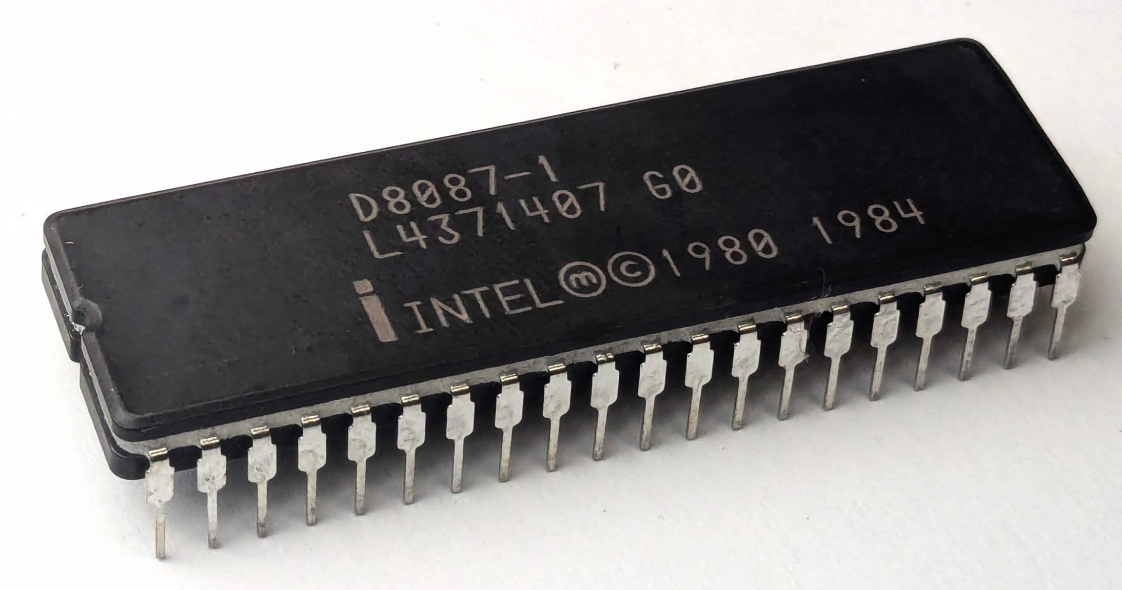
In 1980, Intel introduced the 8087 floating-point chip, a co-processor that made floating-point operations up to 100 times faster. This chip was highly influential, and today most processors use the floating-point standard introduced by the 8087.
The 8087 uses complicated algorithms to accurately compute functions such as square roots, tangents, and exponentials.
These algorithms are implemented inside the chip in low-level code called microcode.
I'm part of a group, the Opcode Collective, that is reverse-engineering this microcode.
In this post, I take a close look at the microcode for one of the 8087's instructions—FXCH—and explain how the microcode works.
The FXCH (Floating-point Exchange) instruction exchanges two floating-point registers. You might expect this instruction to be trivial,
but there's more going on than you might expect; the microcode uses 14 micro-instructions to implement the exchange instruction.
To explore the microcode, I opened up an 8087 chip and created a high-resolution image with a microscope. The large microcode ROM occupies a central position, holding the micro-instructions that control the chip. The microcode engine on the left steps through the microcode, handling jumps and subroutine calls. The bottom half of the chip is the "datapath", the circuitry that performs floating-point calculations; it is split into a 16-bit datapath for the number's exponent and a 64-bit datapath for the number's fractional part (also known as the significand).
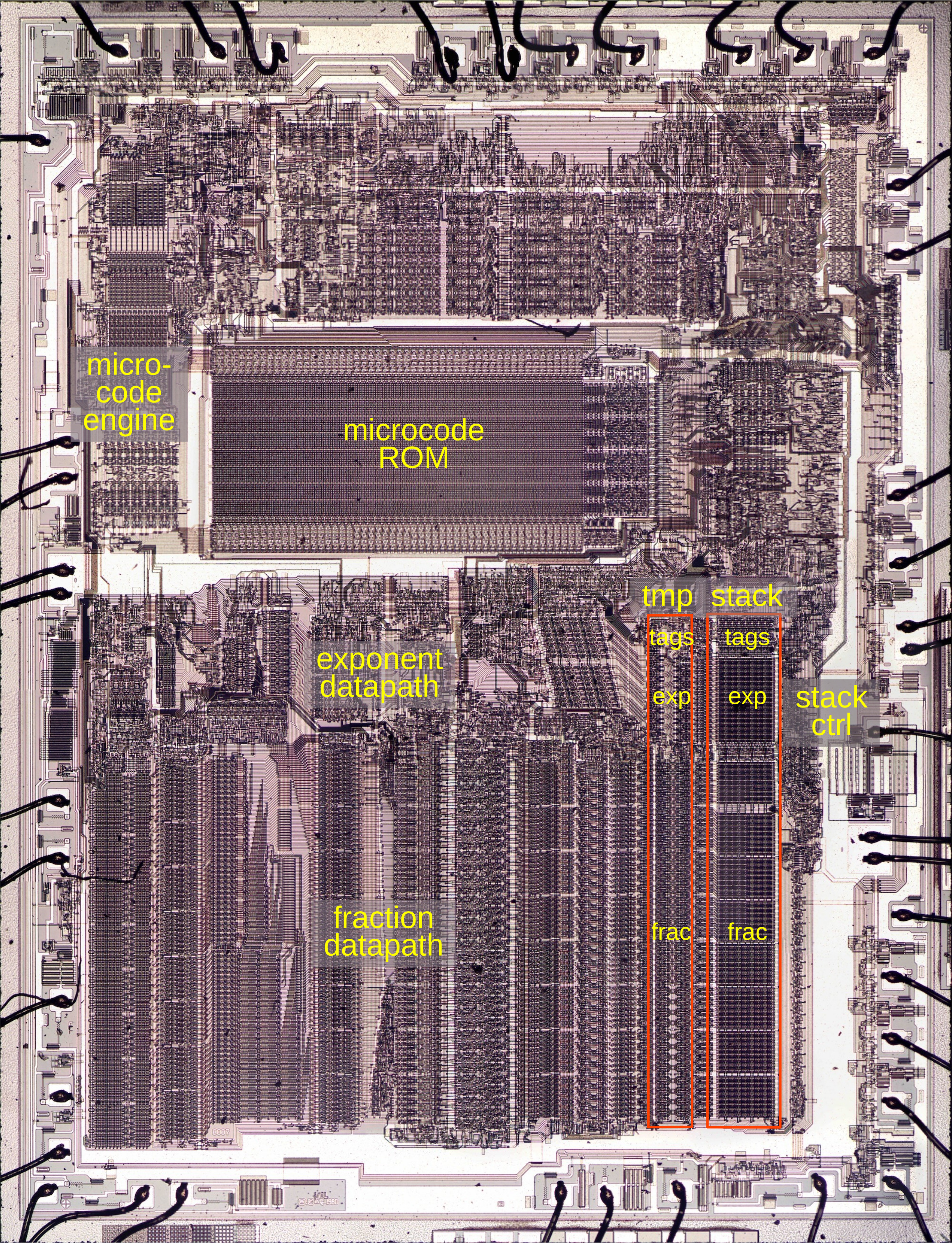
This post focuses on the temporary registers and stack registers that are highlighted in red. The chip has two temporary registers and eight stack registers, each holding a number's exponent and fraction. Each register also has two tag bits that label the type of value in the register. The stack control circuitry at the right manages the stack, keeping track of the top-of-stack position as values are pushed onto the stack or popped off the stack.
The 8087's microcode
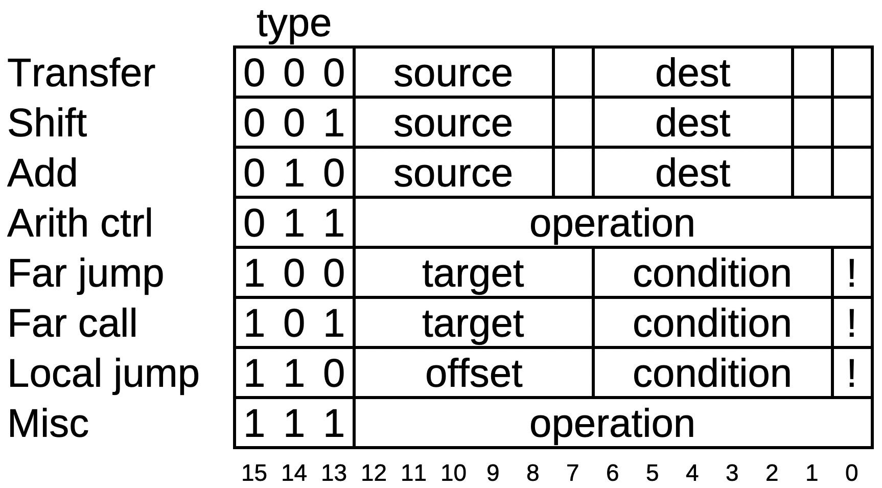
Executing an 8087 instruction such as arctan requires hundreds of internal steps to compute the result. These steps are implemented in microcode with micro-instructions specifying each step of the algorithm. (Keep in mind the two levels of instructions: the assembly language instructions used by a programmer and the undocumented low-level micro-instructions inside the chip.) The microcode ROM holds 1648 micro-instructions, implementing the 8087's instruction set. Each micro-instruction is 16 bits long and performs a simple operation such as moving data inside the chip, adding two values, or shifting data. I'm working with the Opcode Collective to reverse-engineer the micro-instructions and fully understand the microcode (link).
The 8087's micro-instructions are complicated, with many corner cases and ad hoc functions, but I'll provide a simplified overview. Each micro-instruction consists of 16 bits, as shown below. The first three bits specify the type of the micro-instruction, which controls the meaning of the remaining bits. The first type indicates a transfer operation, transferring data from one internal register to another. The two fields specify the source and destination for the data. The three unspecified bits are used for various special cases. Next is a shift operation, which uses the barrel shifter to shift a value left or right. The third type of micro-instruction uses the adder/subtractor. It can also be used in a loop for multiplication or division. Fourth are various arithmetic control micro-instructions that configure the adder, set rounding modes, and so forth. The far jump and far call micro-instructions perform a jump or subroutine call to a target micro-address in a fixed list. The condition field allows conditional jumps/calls based on numerous conditions, while the last bit inverts the condition. A local jump allows a conditional jump to a nearby micro-instruction. Finally, the miscellaneous micro-instructions range from returning from a subroutine or raising an exception to ending the microcode execution.
How values are stored inside the 8087 chip
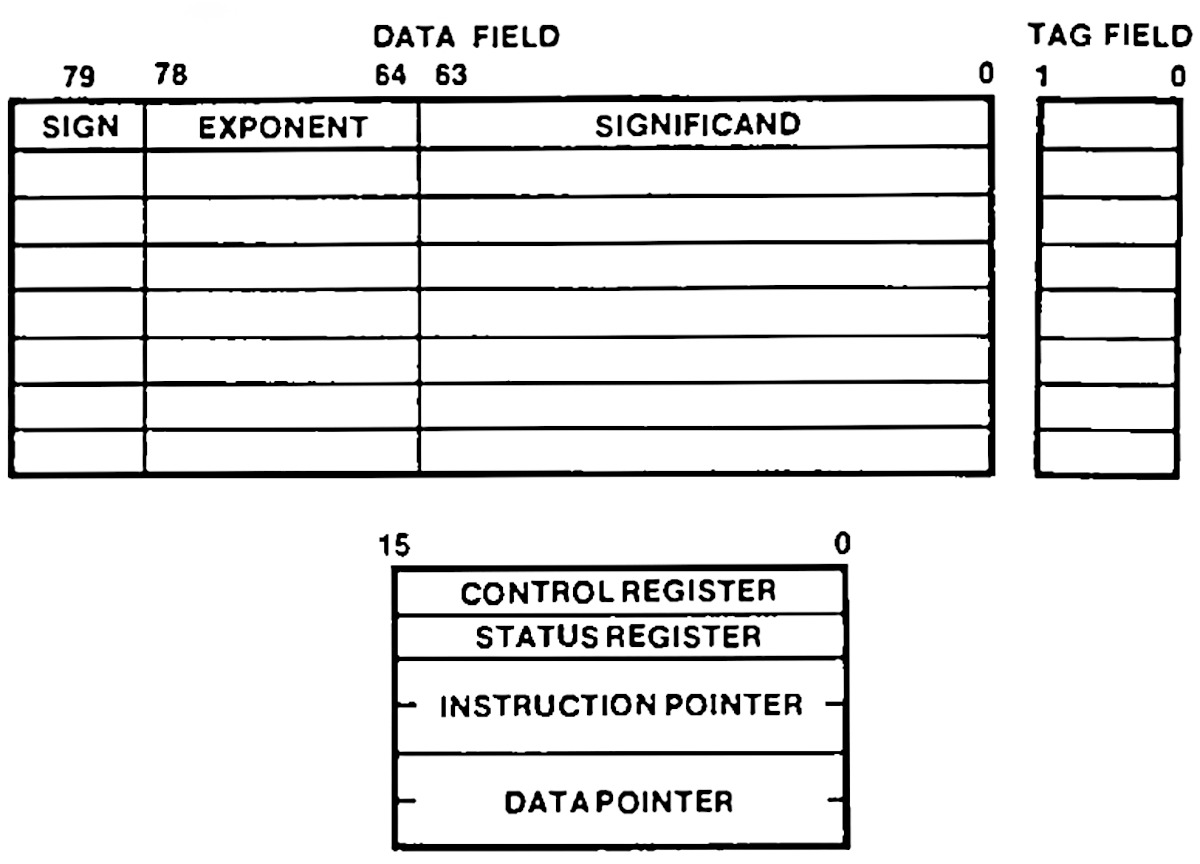
The 8087 supports a variety of data types: floating-point numbers of various sizes, integers, and binary-coded decimal. But internally, everything is stored as an 80-bit floating-point number. A number has three parts: a 64-bit significand (the fractional part), a 15-bit exponent, and a sign bit. The chip has two separate data paths: one for the significand, and one for the exponent and sign.
The chip has eight registers to store numbers during calculations, the top registers in the diagram below.
However, the registers are organized in an unusual way: as a stack, with
numbers pushed to the stack and popped from the stack.
Instead of accessing, say, register #3, you might access the third register from the top of the stack, denoted ST(3); as values are pushed or popped, ST(3) changes.
The stack-based architecture was intended to improve the instruction set, simplify compiler design, and make function calls more efficient, although it didn't work as well as hoped.
Many 8087 instructions act on the top of the stack.
For instance, the square root instruction replaces the value on the top of the stack with its square root.
But what if you want to take the square root of a value in the middle of the stack?
The solution is the FXCH instruction, the focus of this article.
This instruction exchanges the value on the top of the stack with a specified stack position, providing
access to values inside the stack.
One more feature of the 8087 is important to this discussion: each value in the register stack has an associated "tag" value, labeling it as valid, special, zero, or empty. A "normal" floating-point value is tagged as valid. If the floating-point value is infinity, Not a Number, or a denormalized value, then it is tagged as special. A zero value is tagged as zero. Finally, if a register is empty (e.g., its value has been popped off the stack), the register is tagged as empty. The 8087 uses tags to optimize performance and detect errors. For instance, if a programmer pops too many values from the stack and tries to read a stack register that is tagged empty, the 8087 raises an "invalid operation" exception.
The eight stack registers are visible to the programmer, but the 8087 also has temporary registers that it uses internally.
Two of these temporary registers are important for this article: tmpA and tmpB.
Like the stack registers, each temporary register is an 80-bit register, along
with two tag bits.
The FXCH microcode
In this section, I'll explain how the microcode for the FXCH exchange instruction works.
This instruction exchanges the top-of-stack register with the register at a specified position in the stack.
If either register is empty, the instruction will raise an "invalid operation" exception and replace the missing value(s) with the special value "Not a Number" (NaN).
The microcode for the instruction is below, consisting of 14 micro-instructions.2
The first micro-instruction is a transfer, where the source is the top of stack value ST(0) and the destination is
the temporary A register.
The source specification causes the 64 significand to be placed on the fraction bus, the 16-bit
exponent and sign to be placed on the exponent bus, and the two tag bits to be sent to the tag circuitry.
The destination tmpA causes the bus values to be stored into the temporary register.
Thus, the bits in the micro-instruction cause the desired transfer to take place.
The third micro-instruction is similar, but uses a register inside the stack, ST(i), with the index specified in the machine instruction.
FXCH entry point:
#0200 ST(0) -> tmpA           read top of stack
#0201 nop                     Wait a cycle
#0202 ST(i) -> tmpB           Read specified stack register
#0203 if !(tmpA or tmpB empty) jmp #0210 Jump if both registers exist
#0204 set invalid exception   Raise an invalid exception
#0205 if (unmasked) jmp #0213 If interrupt, end
#0206 if !(tmpA empty) jmp #0208 Check if tmpA is empty
#0207 NaN -> tmpA             If so, move NaN to tmpA
#0208 if !(tmpB empty) jmp #0210 Check if tmpB is empty
#0209 NaN -> tmpB             If so, move NaN to tmpB
The happy path and error path continue here:
#0210 tmpB -> ST(0)           Save tmpB to the top of stack
#0211 nop                     Wait a cycle
#0212 tmpA -> ST(i)           Save tmpA to the specified stack register
#0213 RNI                     End of routine: Run Next Instruction
#0214 nop                     Unused
#0215 nop                     Unused
#0216 nop                     Unused
Next, the relative jump at micro-address #0203 illustrates a different type of micro-instruction: the conditional jump.
The micro-instruction specifies a condition, in this case, testing if either temporary register is empty.
(That is, the hardware tests the tag bits associated with the temporary registers to see if either is the "empty" tag.)
The micro-instruction has a bit set to invert the condition.
Finally, the micro-instruction has an offset of +6, yielding the jump target #0210.
The advantage of a relative offset over specifying a full micro-address is that the offset only requires six bits.
(For more information on how conditions are evaluated, see my article Conditions in the Intel 8087 floating-point chip's microcode.)
If either register is empty, the next micro-instruction raises an "invalid" exception. As I'll explain in the next section, you can program the 8087 to either generate an interrupt on an exception or continue processing. The next instruction is a conditional jump that tests if the exception was "unmasked", indicating that an interrupt was generated. In this case, the microcode ends while the main 8086 processor handles the interrupt.
Assuming the interrupt was masked, the microcode now replaces empty values with the special Not a Number value, first checking
tmpA and then tmpB.
The source NaN causes circuitry to pull the exponent bus to all 1's and the fraction bus to all 0's, except for the top two bits.
This particular bit pattern represents Not a Number.3
At micro-address #0210, the empty-register path and the normal path join up to store the temporary registers in the stack registers.
This is where the actual exchange operation happens, since tmpA and tmpB are written to the opposite stack positions from
where they were read.
Finally, RNI (Run Next Instruction) indicates the end of the microcode routine. This stops the microcode
engine and gets the 8087 ready for the next instruction.
The nop (no-operation) microcode instructions are interesting. Each pair of stack reads or writes has a nop in the middle, probably
due to timing constraints on the registers.
The end of the microcode routine has three nop instructions before the next microcode routine starts.
These instructions appear to be wasted space in the microcode; maybe the FXCH microcode was shortened by
three words during development, causing this gap.
Exceptions
The 8087 has a complicated exception system to handle a variety of problems. Exceptions fall into six categories: invalid operation, denormalized operation, zero divide, overflow, underflow, or precision. An invalid operation occurs, for instance, if you take the square root of a negative number or try to perform an operation on an empty register. An overflow exception occurs if a value is too large to be represented, while an underflow exception occurs if a value is too small. A zero divide exception happens if you divide by zero.4 A precision exception occurs if a number cannot be exactly represented as a floating-point number (which is extremely common). Finally, a denormalized exception occurs if a value is too close to zero to be represented with full accuracy.
What happens if an exception occurs? The 8087 allows the programmer to select exception behavior for each exception type. The first option is for an exception to trigger a CPU interrupt, so the software can handle the problem. For instance, the software could attempt to work around the problem, log an error, or simply terminate the program. Alternatively, the programmer can "mask" an exception. In this case, the 8087 continues the operation in a "reasonable" way. For instance, an overflowed value would be set to infinity, while an invalid value would be set to the special value: "Not a Number" (NaN). For a precision exception (e.g., 1/3), the value is rounded. The designers of the 8087 put a lot of effort into continuing after a masked exception in the best way; the manual has pages of details on all the special cases.5
Handling of exception conditions is split between microcode and hardware.
For example, if the FXCH microcode detects an empty register, it executes a set invalid exception micro-instruction.
This micro-instruction sets a latch indicating the invalid exception.
The 8087's control register includes six mask bits, one for each type of exception, blocking interrupts for that
exception type.
The hardware combines the exception flip-flop signals with the mask bits in the control register and the exception flags in the
status register to see if a new, unmasked interrupt has been triggered.
If so, the 8087 circuitry sends an interrupt to the 8086 processor.
On the other hand, if the interrupt is masked, execution of the microcode continues. In the case of FXCH, the microcode replaces empty registers with
the Not a Number value.
Finally, the microcode routine ends with RNI (Run Next Instruction). This triggers many hardware activities, but the relevant one
is copying the state of the exception flip-flops into the status register. This sets the exception bit if the programmer wants to check
it. The exception flip-flops are cleared when the next 8087 instruction starts.
Since the hardware manages the flip-flops, status register, control register, and interrupt line,
the microcode can be simpler and smaller.
Extracting the microcode
The 8087's microcode ROM contains 26,368 bits, specifying 1648 16-bit micro-instructions. At the time, this was a very large ROM; in order to fit it on the die, Intel used a special type of ROM that held two bits per transistor, twice the capacity of a standard ROM. This ROM is semi-analog, using four sizes of transistors to produce four voltage levels. Comparators convert the voltage level to a pair of bits.
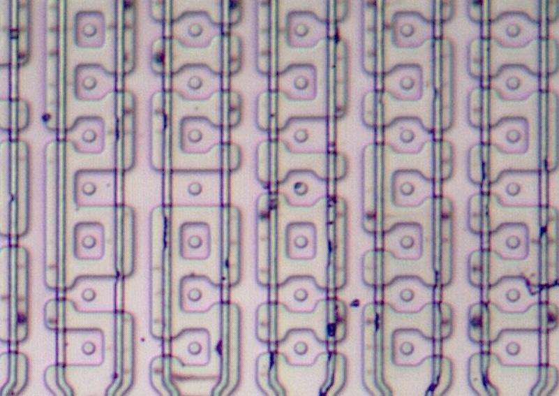
To extract the microcode, I took high-resolution images of the ROM after dissolving the metal layer. Gloriouscow used a neural network to categorize the size of each transistor. (You can explore the full image and transistors here.) The next step was determining how to map the transistors to bits. You might expect that the grid of transistors corresponds to the grid of microcode bits. But due to various hardware optimizations, rows and columns are shuffled and mirrored, which I sorted out by studying the circuitry. The result was the microcode, expressed as a table of 0's and 1's.
The next step was assigning meaning to the microcode. For the 8086 processor, the patent provided a lot of detail on the structure of the microcode and the hardware, but the 8087 patent didn't explain the microcode. Instead, we figured out the micro-instructions through a combination of examining the circuitry, looking for patterns in the microcode, and thinking about how instructions might be implemented.
Microcode is usually complicated, and the 8087 is worse than most. The 8087 was on the edge of what was possible at the time, so the designers resorted to special cases and hacks where necessary. For instance, some conditional jumps have side effects such as updating registers. Other instructions set flip-flops that change the behavior of later operations. We're still working to completely understand the micro-instructions at the hardware level.
I plan to continue reverse-engineering the 8087 microcode; for updates, follow me on Bluesky (@righto.com), Mastodon (@[email protected]), or RSS. I've been working on this with the members of the "Opcode Collective", especially Smartest Blob and Gloriouscow, who converted the ROM images to microcode data and extensively analyzed the contents. See the 8087 repository on GitHub for more.
AI statement: Despite the presence of the em dash, no AI was used in the writing of this article (details).
Notes and references
-
The raw 8087 microcode is available here, decoded by Smartest Blob. I've modified the microcode format for clarity. ↩
-
The 8087 indicates a bad value with a special "Not a Number" (NaN) value. The system allows many different representations of NaN: any value with an exponent of all 1's, a nonzero significand (a zero significand indicates negative infinity), and either sign. For an invalid operation, the 8087 uses one particular NaN value, called real indefinite. For an internal 80-bit real number, this value has the top two bits of the significand set internally, and the rest zero, while the exponent bits and sign are all set. (See pages 87 (S-73) and 90 (S-76).) A 32-bit or 64-bit real uses a slightly different bit pattern for NaN; these number formats have an implied "1" bit for the significand, so only one bit of the significand is explicitly set for the real indefinite NaN. ↩
-
Dividing by zero usually causes a zero divide exception, but 0 ÷ 0 causes an invalid operation exception, while infinity ÷ 0 is valid, yielding infinity. Just one reason why the microcode is so complicated. ↩
-
For more information on the 8087's exceptions, see 8086 Family Numerics Supplement. The exception system is described on page 32 (S-18). The exception flags and exception masks are described on page 24 (S-10). The details of exception handling are described on page 89 (S-75). ↩


5 comments:
First, I'm stunned with the methodology and the way you approached it. Secondly, I loved reading human generated text. Kudos
Nice work!
Once again, your excellent work and extraodinary skills result in a very readable and interesting article; thank you!
So were the 287 and 387 just this but faster, or did they have significantly enhanced instruction sets/microcode collections?
The link to the pdf is dead. Maybe a generated URL; many download sites do that. With a bit of searching I found a working alternative: https://openlibrary.org/works/OL42958721W/The_8086_Family_User's_Manual_(Numerics_Supplement)
Post a Comment